As projected capacitive touch panels continue to expand product offerings in consumer and industrial markets, designers need to become familiar with the trade-offs involved when designing-in a projected capacitive touch panel. A touch panel is not a simple commodity like a resistor or linear dropout regulator, but a complicated subassembly of an electric field generator with a highly sensitive antenna and high optical performance. To achieve optimum performance, designers must consider a number of factors early in the design phase.
“Designing Touch Sensors in 3D,” a previous article featured in Electronic Products , described the general operation of a touch panel and discussed some of the considerations that designers must take into account. However, there are even more details to be considered, such as alternative materials that can be used for constructing a projected capacitive touch panel, the characteristics of those materials, and the functional trade-offs involved.
Most touch panel designs include a cover lens, typically with silkscreen that is used for logos, button labels, and voids for LEDs or photodetectors. Cover lenses can be made from a variety of materials including soda-lime glass, chemically strengthened soda-lime glass, super glass, or plastics like PMMA. When specifying a cover lens, potential characteristics that drive the material choice include hardness, impact strength and safety. For example, soda-lime glass is fairly scratch resistant while PMMA is not. However, soda-lime glass can also be easily broken by a surface impact and may produce dangerous glass shards when it fails. PMMA, on the other hand, is extremely difficult to break with surface impact. Super glass is somewhere in the middle: It doesn’t scratch or break as easily as standard soda-lime glass, but when it does fail, it shatters.
Another consideration when choosing a cover lens material is the dielectric, which is very important to the touch panel designer. The touch panel’s electric field has to propagate through the cover lens: the higher the dielectric, the better the propagation and the thinner the material can be. A good rule of thumb is that a plastic cover lens has to be about half the thickness of a glass cover lens to achieve the same performance (see Fig. 1 ). The touch panel design can typically be adjusted to accommodate a specific thickness of material; however, the materials are not automatically interchangeable. A touch panel that has been designed for a 1.1-mm soda-lime cover lens cannot be replaced with a 1.1-mm plastic cover lens and provide the same performance. The touch panel design will need to be adjusted in some way to accommodate the material of choice. This could be as simple as turning up the gain of the touch panel controller, or it could be as complicated as changing the thicknesses of other layers in the touch panel itself, which would result in a redesign of the overall stack-up.

Fig. 1: Thickness comparison: Glass cover lens vs. plastic cover lens
Cover lenses can also be enhanced with films and/or coatings, including anti-glare (AG), anti-reflective (AR), anti-smudge, etc. Some of these are thin film layers that are applied to the top of the cover lens material while others are chemical etching processes. Each type of film or coating has its benefits and drawbacks. A benefit is the additional durability that coatings can provide for the touch panel. However, coatings may also reduce scratch resistance and some can be applied to glass while others can only be applied to plastic. The good news is that these films and coatings are so thin that they do not alter the performance of the touch panel, so they can usually be added without any impact to the overall design.
The next material to consider is the adhesive used within the layers of the touch panel. Depending on the touch panel design and whether or not the touch panel is being bonded to a TFT, the entire stack-up may include three separate adhesive layers (see Fig. 2 ). Each layer can be a wet or dry bond, and different bonding agents are typically used for each layer. A wet adhesive is a viscous liquid that has to be cured, usually with UV light. A dry bond is typically a sheet adhesive similar to double sided tape. The sheet adhesive may have a plastic base, typically PET, or it may just be a layer of adhesive which is commonly referred to as “no-base” adhesive. 
Fig. 2: Bonding layers
One of the biggest concerns when choosing an adhesive is birefringence. When light passes through materials like PET, different wavelengths in the light are refracted at different angles. This refraction happens in all directions equally, so it’s not noticeable to the human eye. The issue arises when looking at the material through polarized sunglasses, the light rays are aligned in one direction and a prism/rainbow effect occurs across the material. For outdoor applications where the use of polarized sunglasses is possible, PET based adhesives should not be used in any of the internal bonding layers to eliminate birefringence.
Another factor to consider when discussing layer adhesives with the touch panel manufacturer is the temperature range of the adhesives being used. Some adhesives can stretch, which allows air bubbles to form if the temperature gets too high. This might not be an issue for the end application of the product, but it could be a concern during manufacturing, especially if the different bonding layers are being built by different suppliers. One supplier may need a certain cure temperature for their adhesive that is too high for another adhesive layer.
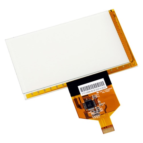
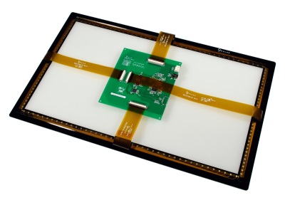
In addition to material selection, there are also mechanical constraints that must be considered. The touch panel controller chip is sometimes on a flexible printed circuit, or FPC, that is attached directly to the touch panel. This is called a chip on flex, or CoF, design (see Fig. 3 ). In other cases, typically on larger touch panels, the controller is on a separate PCB. The PCB has connectors that mate with FPCs connected to the touch panel (see Fig. 4 ). In either case, the placement, size and shape of the FPCs can be a critical factor in the mechanical design of the TFT mounting and the enclosure. This is where a 3D model of the touch panel and controller can be invaluable. With a 3D model you can ensure that there is no interference with the FPCs, or you can use the model to design custom FPCs if needed. One caveat: FPCs are made from a base sheet material. The cost of the FPC is directly related to the number of FPCs that can be created on a single sheet; an FPC that includes bends or right angles is going to lower the number of FPCs per sheet and increase the cost.

Fig. 3: Chip on Flex (CoF) design

Fig. 4: Controller on a separate PCB design
Another factor to consider with FPCs is shielding. While most applications don’t need shielded FPCs, there are some applications that require shielded FPCs either to keep EMI in the environment from affecting the touch panel, or to keep the EMI generated by the touch panel control signals from polluting the system. A shielded FPC is typically a two- or three-layer FPC with a ground plane either on one side or on both sides of the signal layer. Shielded FPCs are much more expensive than single layer FPCs and should only be used when absolutely necessary.
Touch panel manufacturers can help navigate designers through these various options, but only if they are provided with details about the application. The details required include the following:
• Maximum thickness for the touch panel assembly: Be sure to specify exactly what’s included in the dimensions provided (for example, 3.5 mm from the top surface of the TFT to the top surface of the cover lens).
• Are there any impact or safety requirements?
• Is there a requirement for a cover glass coating (for example, anti-reflective, anti-glare, anti-smudge)?
• Is this an indoor or outdoor application? If outdoor, is it possible that users may be wearing polarized sunglasses?
• Are additional bonding steps being performed after the touch panel assembly is received? What are the parameters of those bonding steps (that is, temperature, humidity, pressure)?
• Are there any mounting concerns or restricted areas for the FPCs?
• Are there any special EMI concerns?
The answers to these questions will help touch panel vendors choose the right materials for the touch panel design and avoid costly design impacts that may occur down the road.
Advertisement
Learn more about Ocular LCD


