Required tools:
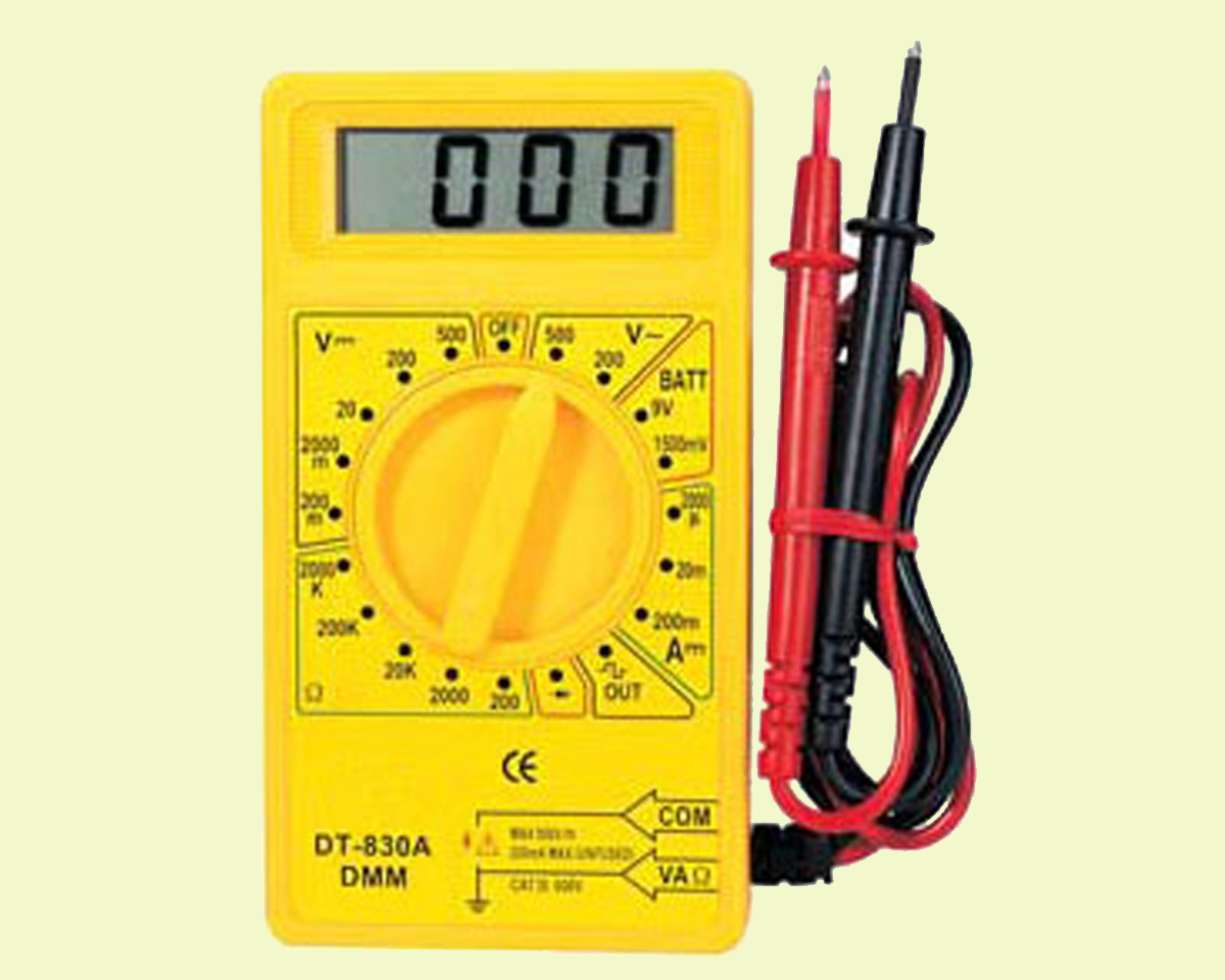
A multimeter
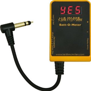
A Tester
Steps:
1. Monitor power supply
2. Test the speaker
3. Check the power amp
1. First, check the fuse and power supply. Take a look at the power section and identify the DC (direct current) voltages. Scour the area for a transformer, a big capacitor, or a rectifier combination. You will find this under the power fuse on the circuit board. Make sure to test the output voltages, that normally fall within the range of 12-0-12 V/0- 12V and 42-0-42/0-80V.
The impetus of checking the voltage is to see if that is in fact where your problem lies. If you receive no voltage then it is time to reassess. By checking out the big capacitors, you can see if there’s a charred appearance that looks like the sign of a “burn-out.” Take a whiff of the section to smell the destroyed part, noticing the difference between the burnt vinyl transformer or burnt electrolyte capacitor and singed silicon diode.
By taking a continuity test of the primary and secondary coils, you can check the transformer. Continuity tests determine whether two points in the amp are connected with zero resistance between them. If the continuity is working, release the mains power and test voltage through the secondary coils, where A/C settings on the multimeter are used. Unplug the unit from the entire mains supply if it appears to not work. If the secondary coil does not receive power when the voltage supply is working, then you need to replace the transformer.
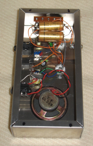
If your transformer appears to be working properly, then you need to take a look at the rectifier. Rectifiers are used in individual diodes or rectifier packs. To see if the rectifier pack is functional, put supply voltage to the input, and then measure the output voltage. If you see that the rectifier is in diode form, then monitor the transient characteristic of diode. Perform continuity checks on both ends of the diode and see if continuity is met. How you know if it’s working correctly is when it performs when polarity is reversed with both ends of the multimeter. If the rectifier or diode malfunctions, then it’s time to replace it.
2. If all of the above-mentioned seem to be working, you now know that the power section is fully efficient, as determined by the supply of power to the circuit. It is now time to check the speaker. Use your multimeter to check the continuity of the speaker. The speaker needs to be replaced if the continuity is open.
3. You now know that the power and end sections are functioning correctly. The next step is to examine the amplifier itself. Guitar amps are generally designed as Cat B/C, as we need to observe the balance of components across “Zero Point.” The “Zero Point” feeds your guitar signal and stays at 0 V. The positive number of input voltage is fed with a power transistor. The negative number of input voltage is fed through its pair. When you determine the balance of components, use a tester to touch the Zero Point before the final stage, and the power transistors are either near or connected to the speaker. If you hear a terribly loud crackling noise, alas, you need a new amplifier. If instead you hear a soft noise, then you need to test each transistor individually.
The power transistor tests depend on the power capabilities of your amplifier and what type of power supply unit you are dealing with. If this is defective, power transistors are replaceable.
Next, look at the voltage amplification, consisting of a physically smaller transistor that is usually a CL or Ck 100. Perform Zero Point tests for the terribly loud crackling noise and smell the surface for burn-outs. Check the core of the pre-amp or transistor, using the Zero Point method to find the faulty section. Take the multimeter, using it to determine transient characteristic of semi-conductors and passive components. Lastly, check the board for breaking areas or cracks.
Advertisement
Learn more about Electronic Products Magazine


