BY STEVE JOHNSON ()
Resistors have been a part of almost every electronic circuit for well over 100 years. During that time, resistors have taken many forms. You can still find early resistors that resembled glass fuses and wood and brass resistance decade boxes filled with precision wound resistance wire. These both were designed for use without the need for tools or meters. They are in sharp contrast to today's color-coded carbon resistors for through-hole mounting and the latest miniature surface-mount resistors that require a microscope and specialized soldering equipment.
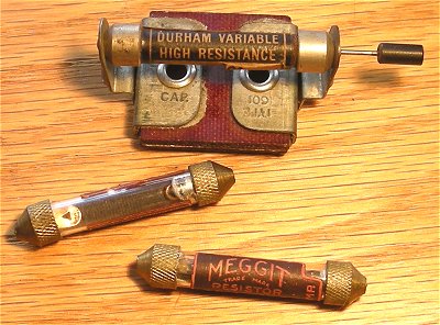
Many early resistors were often mounted in clips for ease of replacement.
Some of the earliest resistors that collectors are likely to find were used in early radio and communications equipment. Many of them resembled a glass fuse with a metal cap on each end. Some had a wire on each cap for soldering point to point in a circuit, but many had pointed end caps that were inserted into a spring clip so they could be easily replaced without any tools since most stores selling radios did not have a service shop, tools, or trained servicemen. For the most part, troubleshooting was done in the store or home by parts substitution. Components that were most likely to fail, like resistors and vacuum tubes, were designed so no tools or soldering were required for troubleshooting or replacement.
Paper labels were used on many of the early resistors to mark a value or a manufacturer's part number. Some early manufacturers in the 1920s hesitated to mark the value on the resistor or even in their service literature. Most likely this was to force the service shop to purchase the resistor by part number directly from the manufacturer instead of buying a generic part of the same value from other suppliers. Due to pressure from service shops, by the early 1930s most manufacturer's had revised their schematics and were marking the values on the resistors or including parts lists showing the part number and value.
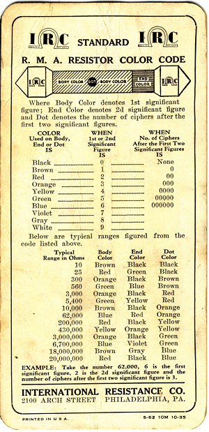
A chart and diagram showing the markings and values of color coded “Dog Bone” resistors.
By the mid 1930s, paper labels were being replaced by painted-on color codes, which would last longer and most likely had become more cost effective to apply in the manufacturing process. The early color-coded “Dog Bone”–shaped resistors did not use the same markings we see today on carbon resistors manufactured over the past 50 years. The value associated with each color was typically the same as the RMA (Radio Manufacturers Association) code we see today on carbon resistors, but instead of a series of colored bands, the value was signified by the body color, end color, and a dot as seen in the 1935 color code chart shown above.
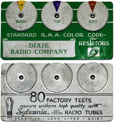
Dog Bone resistor wheel chart.
The resistance wheel chart above, put out by Sylvania, is made from stamped metal. It uses the same color code values used on later carbon resistors, but is marked for the body, tip, and dot format used on the earlier dog bone resistors. The serviceman could spin each wheel to the proper color and read the value. This particular wheel chart was offered as a promotion to radio shops that sold Sylvania vacuum tubes.
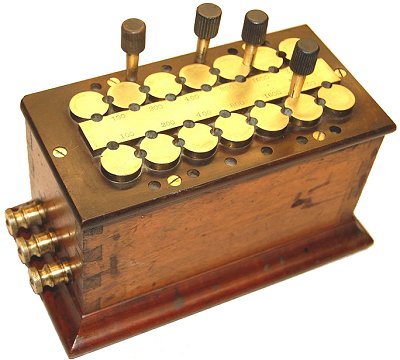
Early brass and wood resistance decade box.
Since resistors of different values were used in most circuits, one of the earliest laboratory and training devices developed was a resistance decade box. Also known today as a resistor substitution box, these decade boxes allowed designers or students to make one connection to the circuit and then choose any resistance values they thought were needed until they got their intended results.
The earliest resistance decade boxes used brass pins inserted between brass contacts to select different value combinations of wirewound spools inside the box. Connection was made by connecting wires from the circuit to large brass posts and knobs. Finding one of these early brass-pin-type boxes in good condition is rare and selling prices usually reflect the demand for early electronics apparatus. Since many were used in training schools, finding one in excellent cosmetic and working condition with no sections burned out is even rarer. Expect selling prices to range between $100 and several hundred dollars depending on electrical and cosmetic condition.
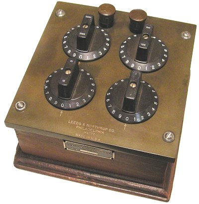
Leeds and Northrup Decade Resistance Box.
Leeds and Northrup was a major supplier of laboratory and training equipment for almost 80 years. Formed in the late 1800s, Leeds and Northrup produced precision electronic laboratory and test equipment for industry and universities.
The Leeds and Northrup decade resistance box shown above is a common item found at swap meets and on line auctions. It has four range selectors covering 0-9 ohms, 10-90 ohms, 100-900 ohms, and 1000-9000 ohms, which allows the user to select any resistance in one ohm increments from 1 ohm to 9,999 ohms. It is very precise and I still use one today for quickly checking the accuracy of the various vintage analog ohmmeters that cross my workbench. Since thousands of these were used by schools and laboratories, they are a common find at swap meets. Expect to find them for a little as $10 in working condition and as high as $80 for a working unit in very good cosmetic condition.
When looking for a vintage decade resistance box at swap meets remember to bring an ohmmeter to quickly test each range position. Frequently, resistance boxes were taken out of service when a tech or student accidently burned out one of the resistance coils. A unit with an open coil has little value.
For more information and examples of early electronic test equipment, view my collection at StevesAntiqueTechnology.com.
Advertisement
Learn more about Electronic Products Magazine


