BY JEFF FALIN, Applications Engineer, Texas Instruments, www.ti.com
With the growing Internet of Things (IoT), remote sensors that monitor the environment and transmit the data back to an Internet connect host system are becoming common. Designing such a sensor to be powered from an energy harvesting power source (for example, solar panel, thermo- or piezo- electric generator to name a few) requires more design time and planning than designing a system with a standard power source (such as a battery or wall adapter). This article provides a step-by-step procedure of how to optimally design an energy harvester-powered remote sensor with transceiver, with Li-ion rechargeable battery so that the energy harvester and battery are sized properly to meet the end application load without overdesigning or adding excess cost. By starting at the system load and working back to the input source, a cost-efficient system with optimally sized components can be designed.
Step 1: Harvester selection
The first step is to choose the appropriate type, but not size, of energy harvester(s) for the application environment in order to maximize the amount of energy actually harvested during non-dark times. The example system we will use for purposes of illustration is a low-power, minimally sized outdoor sensor driven by a solar panel. Other types of harvesters can be used, if the appropriate excitation source (thermal gradients or mechanical vibration) is available.
Step 2: Load minimizing
Consider the solar-powered, outdoor remote temperature sensor as shown in the simplified block diagram of Figure 1 . The most critical step in designing an energy harvesting system is to minimize the system’s load profile by 1) choosing ICs with the lowest power consumption, and 2) operating those ICs in a low duty cycle burst mode.
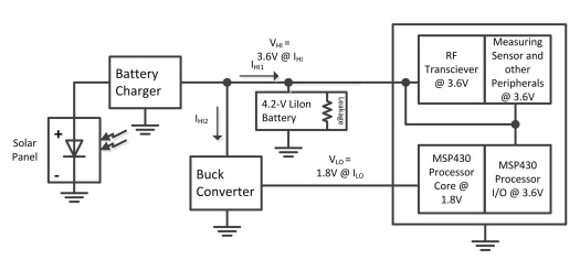
Fig. 1: Remote sensor application
To simplify the calculations, we will assume that the sensor itself, I/O peripherals and RF transceiver are powered directory from a Li-Ion battery with 3.6-V average “HI” rail, while the processor core is powered from a separate 1.8-V “LO” rail.
To reduce total power consumption, the system has two periodic active modes and sleep mode. Measure mode is where temperature measurements are taken for 0.5 s. Immediately following measure mode, transmit and receive mode (TXRX mode) sends and receives data to/from the host for 100 ms every 60 s. The processor enters a low-power sleep-mode while the transceiver and measurement devices are turned off when not in use. The load current profile for the system is shown in Figure 2 .
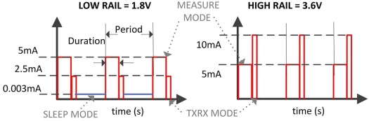
Fig. 2: Load current profiles
Step 3: Power management IC selection
From the load profile we chose the dc/dc converter and/or battery charger with specifications capable of operating within these voltage and current levels, as well as some other key features. Ideally, the power ICs quiescent current is well below the system’s current consumption in sleep mode. Because an energy harvesting source has a much higher impedance output than a typical lower impedance battery or wall adapter, it behaves more like a current source instead of a voltage source. This results in its output voltage collapsing at much lower output currents than would the voltage of a low-impedance (Low-Z) source. Therefore, the dc/dc converter that immediately follows the harvester must manage (limit) its own input current draw so that the harvester’s output voltage does not collapse.
A minimally sized system, including solar panel area, will have as few solar panel cells as possible, outputting 0.6 to 0.7 V each, in series or parallel. Fully charging a 4.2-V Li-ion battery from a buck-based battery charger requires more than 7to 8 cells in series. A boost-based charger allows more flexibility in solar panel configuration and, potentially, fewer solar panels. We choose the bq25570 boost-based battery charger with integrated buck converter because of its maximum power point tracking (MPPT) and input voltage regulation features as well as power levels. The MPPT feature samples the solar panel’s open circuit (unloaded) voltage and stores a user selected fraction of that voltage on a capacitor every 16 s. The input voltage regulation circuit allows the boost converter to pull current from the source until the source voltage drops to that sampled voltage.
Step 4: Compute minimum battery size from load currents
Battery capacity is measured in milliamp-hours (mAh). Sizing the battery to ensure full operation during up to two days of extended darkness (such as cloud cover), we first compute the total current sourced by the battery (IHI1 + IHI2). Using the measured efficiency values for the buck converter from the bq25570 datasheet, we reflect the buck converter load current (ILO) back to the high rail current (IHI2) by solving the efficiency balance equation =POUT/PIN = (VOUT x IOUT) / (VIN x IIN).. Because the solar panel’s operating time is measured in days, we multiply by each mode’s duty cycle and then 24 hours / day to get mAh / day consumed. Table 1 summarizes these computations.
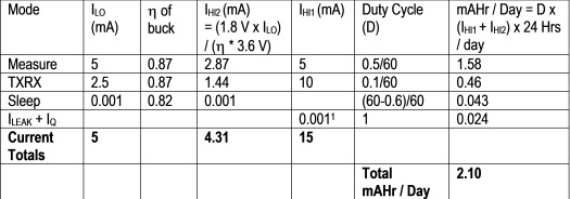
Table 1. Computation of mAh / Day
1 Includes battery leakage current and bq25570 quiescent current
The bq25570 is a good fit given its combination boost charger and buck converter. Also, ILO = 5 mA is well below the 100 mA maximum buck converter output current and 3.6 V * (IHI1+IHI2)TXRX / 0.80 = 86.9 mW is well below the 510 mW maximum input power for the boost converter.
With two dark days, the absolute minimum battery capacity required for the remote sensor to continuously operate is 2 days x 2.10 mAh /day = 4.20 mAh. A battery with slightly higher capacity is recommended so that the battery does not completely discharge at the end of the dark time in order to provide some safety margin.
SIDENOTE :
If we want to use a super capacitor that is fully charged to 4.2 V, but not allowed to drain below 2.5 V, we solve the equation below for CSUPER
3.57 mAh / 1,000 x 3,600 s/hr x 3.6 V = 1/2 x CSUPER x (4.2 V2 – 2.5 V2)
And get CSUPER = 11.2 F.
Step 5: Determine solar panel size
Multiplying the 2.10 mAh / day by the 3.6-V average battery voltage gives a system need of 7.56 mWh / day. If the solar panel provides power to the bq25570 boost charger 24-7, then with its 80% average efficiency, the system could run from the boost charger output, without a battery – if the solar cell provided 7.56 mAh / day / 0.8 = 9.45 mWh /day.
However, we are only charging 5 out of 7 operating days a week and only for 4 h/day, with the battery providing power during the 2 dark days and during the non-charging hours. This means the solar panel must provide extra power to charge the battery for a total of 9.45 mWh/day x 7 days / 5 days / 4 h/ day = 2.65 mW. Assuming a small solar panel that provides 0.025 W/cm2 at minimal lux is available, then we only need 2.65 mW / 0.025 mW/cm2 = 132 cm2 of solar panel area.
SIDENOTE : Remembering secondary school’s “cancel the unit’s” trick really helps.
Optimizing a rechargeable battery-powered system with solar re-charging can be accomplished in five easy steps:
1. Harvester selection for the application environment
2. Minimizing the load by running the system at a reduced duty cycle
3. Selecting an optimal power management IC
4. Sizing the battery to provide power during the dark times
5. Determining the minimum solar panel size needed
By starting with the system load and reflecting the output system power backwards to the harvester output using efficiency power balances, we can determine the optimal size for the batteries and solar panel – thereby reducing total cost and solution size.
References
Download the bq25570 datasheet.
Here’s more information about the Internet of Things.
Advertisement
Learn more about Texas Instruments


