BY GINA BONINI
Technical Marketing Manager
Tektronix, www.tek.com
The largest and perhaps most dynamic market for oscilloscopes is the midrange: scopes that slot between basic models that support education, budget-constrained hobbyists, and service applications, in addition to performance models used for high-speed research and development. Midrange oscilloscopes combine affordable pricing with a rich feature set and solid performance, helping to make them a mainstay on design engineers’ test benches around the world.
Over the past two decades, the midrange scope market has seen a tremendous amount of innovation, driven by changing market requirements. As the timeline in Fig. 1 makes clear, oscilloscope innovation maps closely to embedded design and technology trends.
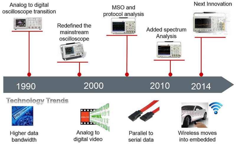
Fig. 1: This timeline shows how technology trends have been driving innovation in midrange oscilloscopes over the past two decades. The latest innovation maps to the need for integrated instrumentation to support system-level debugging of highly integrated, wireless-enabled designs.
The ‘90s were characterized by the shift from analog to digital scopes, along with the move to faster microprocessors. As the market moved from parallel bus technologies to more streamlined, lower-cost serial solutions, mixed signal oscilloscopes (MSO) became the instrument of choice for debugging system level issues. Then two years ago, Tektronix pioneered the mixed-domain oscilloscope (MDO) that adds advanced spectrum analysis in response to the explosive growth of wireless in embedded system designs.
Since their introduction, the MDO4000 series oscilloscopes have started to move solidly into the mainstream. So much so that the RF-capable oscilloscopes are now replacing mixed-signal oscilloscopes in the midrange product lineup, just as the mixed-signal oscilloscopes replaced analog-only oscilloscopes. The reason is simple: From input devices like mice and keyboards to smart homes and streaming media boxes, consumers demand the convenience of wireless. In response, designers need improved RF test support from their test equipment. Even for designs without wireless technologies, engineers are facing EMI and noise issues requiring frequency domain analysis. With MDOs now priced comparably to MSOs with similar performance, it’s not hard to understand the growing popularity of MDOs.
A scope and much more
But wireless integration isn’t the only thing that’s changing. With complexity on the rise, modern mixed-signal designs are proving to be a worthy adversary to designers. Embedded-system design engineers are having to wear multiple hats in order to efficiently troubleshoot and debug the latest designs. This means tackling such activities as designing power supplies and measuring power efficiency, or having to track down sources of noise.
In a survey of oscilloscope users, Tektronix found that in addition to their oscilloscopes, engineers reported that they turned to the following instruments several times per month:
• Digital voltmeter, 87%
• Function generator, 68%
• Spectrum analyzer, 45%
• Logic analyzer, 33%
• Protocol analyzer, 15%
What this indicates is that there is a need for the oscilloscope to give designers a more comprehensive set of functions and features to support efficient verification and debugging of embedded system designs.
To meet this need, Tektronix recently introduced the MDO3000 series integrated oscilloscopes. These instruments combine six instruments in a single small, portable package able to provide insights in both the time and frequency domains (Fig. 2 ). The series provides two or four analog input channels with bandwidth ranging from 100 MHz to 1 GHz, 16 digital channels, and one RF input channel matching the bandwidth of the oscilloscope (9 kHz up to analog bandwidth). The RF input frequency on any model can be extended to 3 GHz. The scopes also provide extensive debug functionality; along with Wave Inspector controls and more than 125 available trigger combinations, the scopes’ FastAcq feature can capture 280,000 waveforms per second to assist in finding infrequent anomalies in a signal.
Further, starting from the entry-level scope, users can upgrade their instrument to the analog bandwidth and spectrum analyzer input frequency of the highest-performance scope in the line. Functional upgrades include the addition of 16 digital channels, protocol analysis, arbitrary function generation, or digital voltmeter measurements.
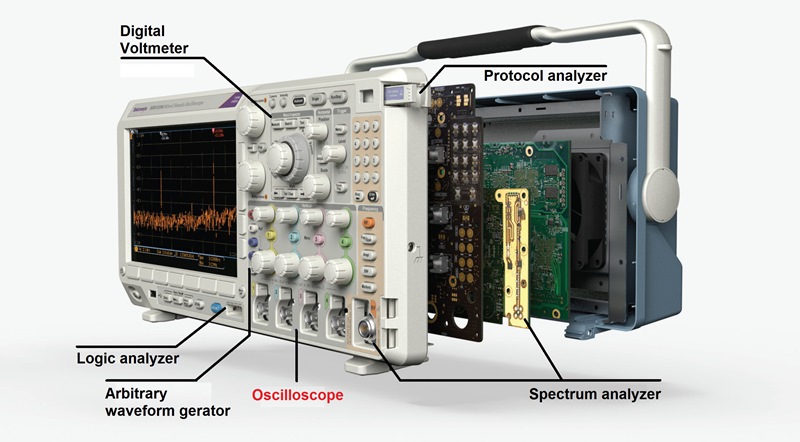
Fig. 2: While still performing the full functions of an oscilloscope, the MDO3000 series adds the functionality of numerous instruments to simplify engineering measurement for the majority of designs seen today.
The integration of additional instrument capabilities into the scope results in automated serial and parallel bus analysis as well as optional automated power measurements. Also available are optional serial protocol analysis packages including I2 C, SPI, RS-232, USB 2.0, CAN, LIN, FlexRay, MIL-STD-1553, and Audio. The integrated, optional 50-MHz arbitrary function generator (AFG) functionality is more than two times faster than competitive offerings with eight times the arbitrary waveform record length. The integrated digital voltmeter (DVM) provides four-digit AC RMS, DC, or AC+DC RMS voltage measurements, as well as five-digit frequency measurements. It is available for free when the product is registered.
Low-capacitance 3.9-pF passive voltage probes are includes with the scopes, and 1-GHz passive voltage probes are standard with 1-GHz instruments. Historically, passive voltage probes have been 12 pF or higher capacitance, but low-capacitance probes minimize the impact on measurements by reducing loading on the device under test, while also reducing signal distortion and cleanly passing the signal to the oscilloscope.
FFT vs. spectrum analyzer
It should be acknowledged that many mid-range oscilloscopes have the capability of calculating and displaying a fast Fourier transform (FFT) of an acquired time-domain signal. On the surface, this would seem to provide adequate frequency-domain analysis capabilities for many users. However, the typical oscilloscope, even with FFT capability, is at best a poor substitute for a spectrum analyzer for looking at spectral information.
One significant challenge is bandwidth limitation: The spectrum of the signal can only be acquired up to the bandwidth of the oscilloscope. To see a full 3-GHz spectrum, for instance, requires an expensive 3-GHz-or-higher-bandwidth oscilloscope. Other issues include low signal fidelity (making it difficult to measure small signals in the presence of larger ones), limited spectral analysis capabilities, and a user interface designed for time-domain measurements.
As is the case for MDO3000 oscilloscope, the limitations can be avoided by incorporating a dedicated spectrum analyzer into the scope, thus providing much improved spectral fidelity and usability. At the same time, by leveraging oscilloscope acquisition technology, the scope can provide very wide capture bandwidth, a performance advantage even when compared to entry-level standalone spectrum analyzers.
Spectral analysis in the scope
When using the spectrum analyzer input, the scope display becomes a full-screen frequency domain view (Fig. 3 ). Key spectral parameters such as center frequency, span, reference level, and resolution bandwidth are adjusted using the dedicated front-panel menus and keypad.
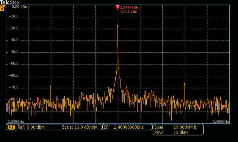
Fig. 3: When using the spectrum analyzer input, the MDO3000 display becomes a full-screen frequency domain view.
It can be a tedious task to turn on a traditional spectrum analyzer and place enough markers to identify all the peaks of interest. The MDO3000 Series improves this process by automatically placing markers on peaks that indicate both the frequency and the amplitude of each peak. The user can adjust the criteria that the oscilloscope uses to automatically find the peaks. The instrument also includes a spectrogram display (Fig. 4 ) for monitoring slowly changing RF phenomena. The x axis represents frequency, just like a typical spectrum display. However, the y axis represents time, and color is used to indicate amplitude.
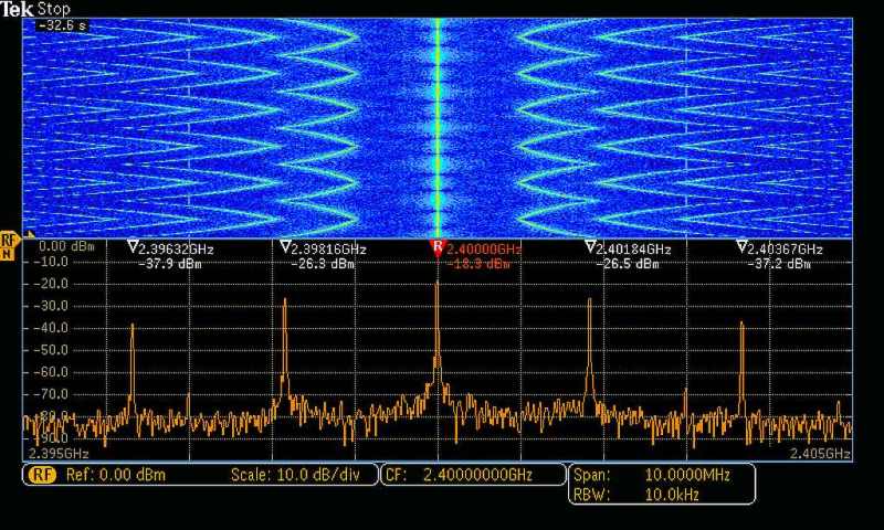
Fig. 4. The spectrogram display illustrates slowly moving RF phenomena. As shown here, a signal that has multiple peaks is being monitored. As the peaks change in both frequency and amplitude over time, the changes are seen in the spectrogram display.
Modern wireless communications vary significantly with time, using sophisticated digital modulation schemes and, often, transmission techniques that involve bursting the output. These modulation schemes can have very wide bandwidth as well. By providing up to 3 GHz of capture bandwidth, the scope can generate the spectrum display from a single acquisition, thus guaranteeing the user will see targeted events in the frequency domain.
Signal input methods on spectrum analyzers are typically limited to cabled connections or antennas. But with the optional TPA-N-VPI adapter, any active 50-Ω TekVPI probe can be used with the MDO3000’s spectrum analyzer. This enables additional flexibility when hunting for noise sources and enables easier spectral analysis by using true signal browsing on a spectrum analyzer input. In addition, an optional preamplifier accessory, which provides 10-dB nominal gain across the 9-kHz to 3-GHz range, assists in the investigation of lower-amplitude signals.
Scope-based AFG
The scope’s optional integrated arbitrary function generator can be used for simulating sensor signals within a design, or adding noise to signals to perform margin testing. The integrated function generator provides output of predefined waveforms up to 50 MHz for sine, square, pulse, ramp/triangle, DC, noise, sin(x)/x (Sinc), Gaussian, Lorentz, exponential rise/fall, Haversine, and cardiac.
The arbitrary waveform generator includes 128 kpoints of record for storing waveforms from the analog input, a saved internal file location, a USB mass storage device, or from an external PC. Once a waveform is in the edit memory of the arbitrary waveform generator, it can be modified via an on-screen editor (Fig. 5 ) and then replicated out of the generator.
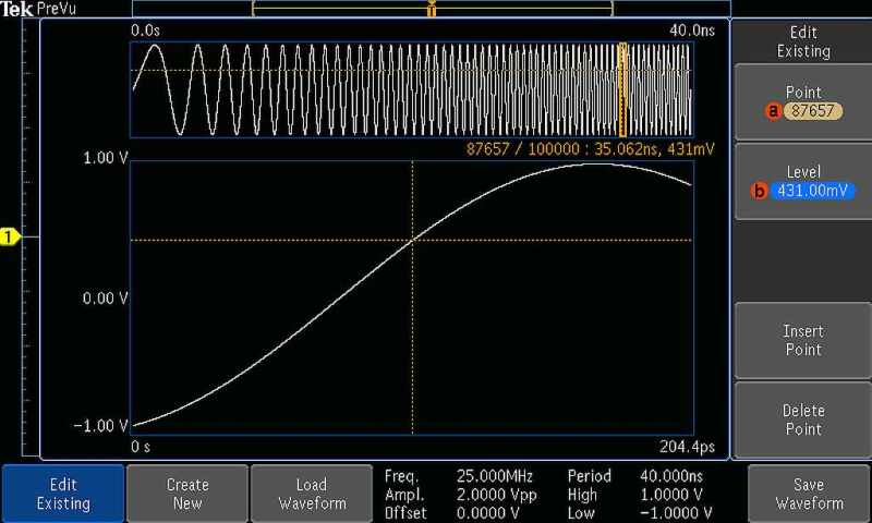
Fig 5: Arbitrary waveforms stored in memory can be edited using the MDO3000’s point-by-point editor.
DVM, and frequency counter.
Another new feature is an integrated 4-digit digital voltmeter (DVM) and 5-digit frequency counter. Any of the analog inputs can be a source for the voltmeter, using the same probes already attached for general scope usage. The display provides both numeric and graphical representations of changing measurement values. The display also shows minimum, maximum, and average values of the measurement as well as the range of values measured over the previous five second interval.
As an example, the input voltage (yellow) and current (blue) from an ac-to-dc converter is shown in Fig. 5 . The DVM was turned on to monitor the dc output voltage. The measurement statistics at the right side of the DVM display indicate that the output voltage is very stable, and the graphical readout provides a visual indication of voltage variations.
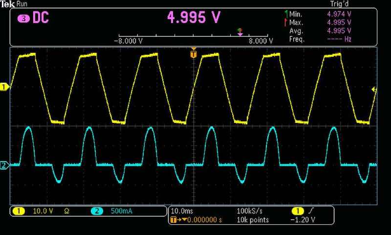
Fig. 6: When monitoring a dc output voltage of an ac-dc converter with the DVM, the ac input voltage waveform (yellow) and the current waveform (blue) can also be shown.
The future of scopes?
Is an integrated oscilloscope right for you? As always, your mileage may vary according to your needs and requirements; be sure to take a close look at spec sheets in comparison to your intended applications. But with prices coming down to match “standard” digital oscilloscopes and wireless becoming commonplace in embedded systems, it’s safe to say that integrated oscilloscopes are here to stay, and indicate where oscilloscopes are headed.
About the author

Gina Bonini is a technical marketing manager for Tektronix. She has worked extensively in various test-and-measurement positions for more than 20 years, including product planning, product marketing, and business and market development. She holds a BSChE from the University of California, Berkeley, and an MSEE from Stanford University.
Advertisement


