BY DAVID WYBAN
Applications Engineer
Keithley Instruments
www.keithley.com
Testing high power, high brightness light-emitting diode (HBLED) modules is increasingly challenging. One crucial characterization function is the ability to detect which modules are affected by the thyristor effect, so that they can be sorted out during production test. The thyristor (or snapback) effect is simply an unwanted capacitance in series with an LED's junction. This effect is problematic because it causes a delay in the turn-on of an LED and it demands a higher LED turn-on voltage, neither of which is a desirable quality. For anyone who manufactures LEDs or designs them into their products, the delay in turn-on is the most serious problem because it creates undesirable inconsistencies in the level of the light output, which can be seen as a dimming or a shift in the color of the light output when compared with the output of LEDs that does not exhibit this effect. The higher LED turn-on voltage required means power is wasted (current times voltage equals power, so requiring a higher voltage to achieve the same current equals higher power). Given that current is delivered to the LED via pulses, the LED is switched on and off hundreds or thousands of times a second, so the cumulative amount of wasted power due to the thyristor effect can be quite significant.
A short description of the elements of a high power HBLED module may be helpful in understanding what’s involved in testing for the thyristor effect. HBLEDs are commonly defined as LEDs that operate at 1W of power or more, but HBLEDs typically operate at 2 to 3 W and run on 300 mA to 1 A of current sourced through large-gauge leads. They are often mounted on a small thermally conductive board designed to draw heat away from the LED's junction. Despite their relatively high brightness, individual HBLEDs are not bright enough for use in most lighting applications. Instead, multiple HBLEDs are commonly combined together to create a single luminaire, such as an LED light bulb for a retrofit application or an entire lighting fixture. This works well in most applications because it's desirable to have the light spread in multiple directions, and the size of the luminaire provides sufficient space for multiple HBLEDs.
However, this approach is unsuitable for applications where space is limited and/or if the light needs to be directional. The demand for a lot of light in a small package has led to the development of high power LED modules, which consist of one or more large-die high brightness LEDs. When multiple die are present, they could be wired either in parallel or in series, depending on the application. The die of these LEDs are much larger than the die of typical HBLEDs and can handle much larger currents as well. A single die often must be able to withstand currents of 10 A or more. Those high current levels demand the ability to dissipate lots of heat. Operating temperatures for these modules are commonly rated as high as 140°C, so they are typically built on a heavy copper core board or other thermally conductive material to pull the heat out of the LED's junction. The board or other material is mated with a heat sink of the appropriate size.
Today's high power HBLED modules are capable of DC power levels approaching 100 W. They are typically operated in a pulse mode, in which the pulse power commonly exceeds 100 watts. These pulse specifications are also typically at high duty cycles of 50 percent as well. Because of the high power of today’s LED modules and components, any manufacturing defect that causes an increase in power consumption is a particularly important concern.
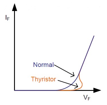
The thyristor (or snapback) effect can affect all LEDs, not just high power HBLED modules. A thyristor is simply an unwanted capacitance in series with an LED's junction. When an LED has a thyristor, for a given forward current (IF ), the measured forward voltage (VF ) will be the voltage across the LED's junction plus the voltage across the unwanted capacitor (VF = VLED + VCapacitor ). In a plot of forward voltage vs. forward current, the additional voltage from the capacitance shows up as a kink in the curve (Fig. 1 ). Here, a normal VF –IF curve from an LED that does not exhibit the thyristor effect is illustrated in black; the orange curve shows the VF –IF curve of an LED without the thyristor effect.

Fig. 1: The thyristor effect appears as a kink in an LED’s VF-IF curve .
LEDs that exhibit the thyristor effect will have a greater forward voltage than expected for a given forward current, compared to an LED that does not exhibit it. However, detecting them can be difficult as thyristors have a tendency to charge up and then break down rapidly as current is pulsed into the LED. If the test equipment used isn’t capable of measuring the forward voltage as soon as the current pulse settles at its peak, it’s easy to miss the presence of a thyristor effect entirely.
Thyristors effects are temperature dependent; they are more pronounced at lower temperatures because the reduced thermal excitation makes it more difficult to overcome the capacitive barrier. In addition, thyristors are affected by ambient light and the capacitive barrier is easily overcome by photo-excitation. Therefore, it is easiest to detect a thyristor effect when the LED is cold and placed in a dark environment.
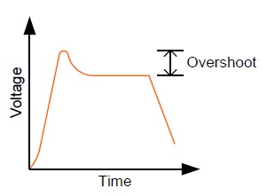
To complicate matters further, thyristor effects simply don’t appear at all current levels. Instead, they're most detectable only at certain current levels, so it’s all but impossible to find them in single shot measurements. However, equipment that allows capturing a complete waveform makes it possible to observe the charge and then breakdown of the thyristor, which will appear as an overshoot in a voltage waveform. If an overshoot greater than 0.1V appears, it’s likely due to the thyristor effect (Fig. 2 ).

Fig. 2: A significant overshoot in the voltage waveform indicates the presence of the thyristor effect .
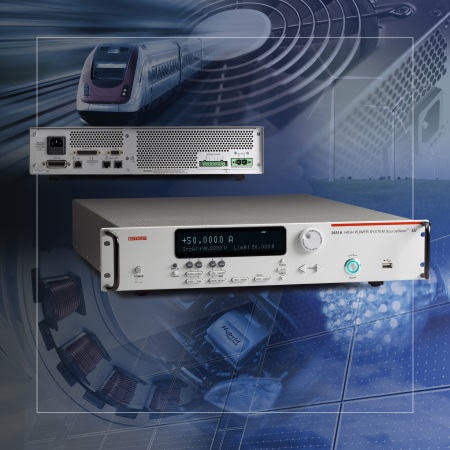
There are several instrumentation options for capturing the waveform in order to detect the thyristor effect. Although the most common ways include using an oscilloscope or a high speed data acquisition unit, a specific model of either one might not offer sufficient resolution to detect short duration events. In contrast, a tightly integrated, high power sourcing and measurement instrument is able to address both the application’s high power and high resolution requirements. For example, the Keithley Model 2651A High Power System SourceMeter Source Measure Unit (SMU) Instrument (Fig. 3 ) includes an 18-bit fast sampling A-D converter capable of digitizing the waveform at a rate of one mega-sample per second. It also offers the advantage of allowing waveform analysis to be performed right on the instrument itself using a test script embedded in the instrument. That allows identifying an LED with the thyristor effect without the need for an external controller.

Fig. 3: The Model 2651A High Power System SourceMeter Instrument is designed to characterize and test high power electronics and components, including high power HBLED modules .
To learn more about these devices and how to test them, see the author’s online webinar on this topic, Meeting the Electrical Measurement Demands of High Power, High Brightness LEDs.
Advertisement
Learn more about Keithley Instruments


