The DS2406 comes in two packages, a 3-pin TO-92 package and a 6-pin TSOC package. The TO-92 version consists of a single PIO channel, while the TSOC package consists of two PIO channels. The PIO provides input and open-drain output capabilities. A pullup resistor is required for output operation as shown in Figure 1.
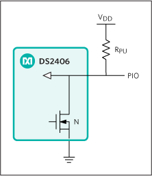 Figure 1. PIO supports digital input or open-drain output.
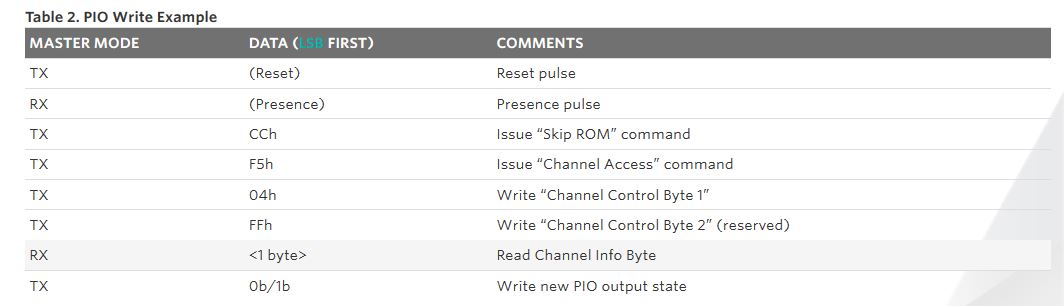
The basic write example configures the DS2406 for single-channel output mode. The Channel Control Byte 1 (see Table 1) configures the output state of the PIOs. The TOG bit selects between two states: fixed read or write mode, or toggling between read and write. Here, set TOG to 0b, since we desire the pin to always be configured as an output. The IM bit or initial mode is in reading mode when set to 1b, or writing mode when set to 0b. Set IM to 0b for writing (output) mode. The IC bit is the interleave control, this does not have an effect for single-channel usage, we set this to 0b. The CHS bits select which channels the device will use. To select Channel A only, set CHS[1:0] to 01b. Disable the activity latch and CRC option by setting ALR, CRC1, CRC0 to 0b. This results in the byte value of F5h.

The basic control routine is listed in Table 2. First, use a 1-Wire® initialization sequence with a ROM command such as “Skip ROM” followed by a device-specific command. The Channel Control Byte 1 is F5h, while byte 2 should always be set to FFh and is reserved for future use. The return value is the channel info byte. After this, transmit either desired output state of the PIO. Use the write bit command to send the desired output state. (For single-channel operation only, you can use 00h for low or FFh for high. The state of the most significant bit determines the output state.) You can change the output state as many times as necessary, until a 1-Wire reset command is sent.
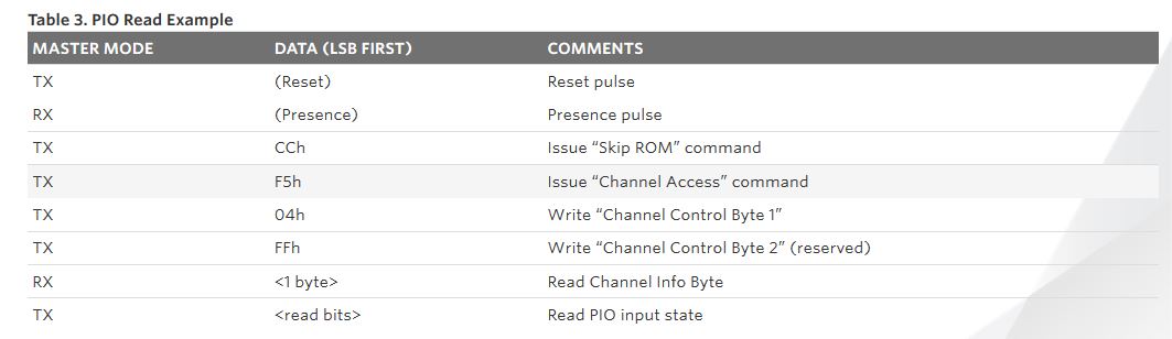
For reading, change the IM bit from 0b to 1b for a channel control byte of 24h (see Table 3). When the 1-Wire master reads a bit from the device, it will return the state of the input pin. The master can query the device as many times as necessary until a 1-Wire reset command is sent.
The DS2406 data sheet contains more information on how to utilize the other modes. This application note should help you start testing the DS2406 by using this basic mode of operation.
1-Wire is a registered trademark of Maxim Integrated Products, Inc.
Related Parts
DS2406 Dual Addressable Switch Plus 1Kb Memory Free Samples
Advertisement
Learn more about Maxim Integrated


