Segmented liquid crystal displays (LCDs) provide visual information to users in a wide variety of applications from smart meters to electronic shelf labels (ESL) to medical equipment and consumer electronics. These types of products all require a display to provide a modern, easy-to-understand user interface that constantly updates user information in real-time. Choosing a microcontroller (MCU) with built-in low-power LCD driver circuitry to directly control the LCD glass reduces design complexity and board space by integrating the functionality into a single system controller. Keeping LCD segments turned on requires constant ac-signal generation, so it may be an energy drain in battery-powered, energy harvesting or power-sensitive applications. It is particularly important to use an MCU that can automatically generate ac signals even while remaining in low-power sleep modes to consume as little current as possible. This article discusses how LCDs operate and includes potential design considerations for a low-power LCD microcontroller application.
How LCDs work
The structure of a segmented LCD display essentially consists of the components featured in Figure 1. It includes: two polarizers rotated 90 degrees from each other to polarize light coming into the display; liquid crystals between the polarizers with electrodes to apply a charge; and a reflective backing to reflect light that gets through all the layers of the display.
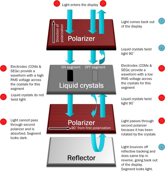
Fig. 1: The basic structure of an LCD consists of two polarizers, liquid crystals and a reflector.
LCDs must be driven with ac signals; a dc-level on an LCD segment can damage the LCD. Instead, the root mean square (rms) voltage presented on an LCD segment determines whether it is on or off. Microcontrollers with integrated LCD driver modules generate these types of ac waveforms automatically, so the user only has to specify if a segment should be on or off while the internal hardware does the rest. LCD segments have a charge applied to the liquid crystals between two electrodes – a common (COMx) line and a segment (Sx) line. The potential difference applied by these two electrodes creates the waveform ultimately seen by the LCD segment.
Layout considerations
LCD drive lines use constantly switching ac signals to keep the image on the display with no dc level, so they should be kept away from any noise-sensitive lines on the board (like the external crystal connections). Guard rings can also be used to help shield noise-sensitive lines like the crystal connections or ADC inputs from noise coupling, and having a ground plane underneath the LCD traces and guard traces can also provide shielding.
A good practice is to keep all LCD signal traces (segment and common lines) together similar to a data bus. Keeping the LCD layout in a single layer can also be helpful to ensure there are no LCD traces running over or under potentially sensitive traces. If the microcontroller requires a capacitor for an internal charge pump for LCD voltage generation, it is also recommended to keep the capacitor as close as possible to the MCU pin with a short trace.
There are typically two different ways to approach LCD layout – a hardware-driven approach and a software-driven approach. A hardware-driven approach to layout might involve simply connecting the LCD glass pins to the closest MCU pins on the board capable of LCD function. This method can be used to minimize crossings and try to layout all connections in a single layer. However, a purely hardware-driven approach may mean the pins are mapped scattered across the MCU LCD memory, requiring more software work and overhead when writing the code.
Conversely, a software-driven approach would select the segment pin connections based on how the MCU LCD memory is laid out internally in the microcontroller. This might include making pin selections such that a full digit or alphanumeric character can be updated on the display with a single byte or word write to LCD memory for efficient code. The LCD glass and memory mapping from the TI MSP-EXP430FR4133 LaunchPad evaluation kit are used as an example in Figure 2. However, using a software-driven approach may cause a more complex layout or require a multi-layer board. This can easily be avoided by selecting an MCU that allows reconfigurable LCD pins.
Most designs use a combination of hardware- and software-driven layout methodologies.
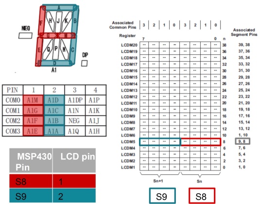
Fig. 2: Example of a software-driven pin selection on a TI MSP-EXP430FR4133 LaunchPad evaluation kit.
Software considerations
Writing an LCD driver program can seem daunting since there are so many hardware factors that the software must handle. The LCD display glass being used, its layout properties, the choice in connection between the LCD pins on the display and the LCD pins on the MCU, and also how the microcontroller maps the pins to display memory can make code confusing and hard to read without having the full picture and several datasheets handy.
Creating a lookup table containing commonly displayed data, such as numbers and characters, can make your code much easier to read. For example, if numbers will be displayed on the LCD, create a lookup table containing the values to write into the LCD memory registers to display each digit 0-9. This will make the code much easier to read than simply writing a hex value into memory – for example, to write the digit 2 with a lookup table might be: “LCDM5 = digit[2];”
Since the LCD memory on the MCU typically maps to particular LCD pins, which then are connected to different pins on the LCD display, it can be difficult to know which LCD memory to set in order to display a character in a particular location on the display. To help, create #defines for your LCD to let you reference the correct LCD memory by typing the name of the LCD display digit position you are trying to set. For example, in Fig. 3, the entire digit for position A1 from the LCD datasheet is set using the LCDM5 register due to the pin connections on the board. Using #define A1 LCDM5, now the code can simply be written A1 = digit[2]; to write the digit 2 in position A1 on the display. This makes it much easier to write and understand the code while simply looking at the LCD datasheet, rather than having to track what memory locations map to particular digits on the display.
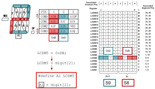
Fig. 3: Use of #defines and Lookup Table
LCD configuration options vs. power consumption
Typically there are a number of configurable options for LCD configuration in the microcontroller’s LCD driver, including voltage, biasing and frame frequency settings. It is important to understand how these different options affect performance and power consumption in order to weigh the tradeoffs for a particular application.
Using a lower frame frequency will typically use less power because the LCD segments are not switching as often – however, if the frame frequency is too low the display may appear to flicker.
Typically the LCD bias voltages (the fractional voltages used to generate the LCD AC waveforms) are divided down from the main LCD voltage VLCD using a resistor ladder to produce these fractional voltage levels (1/3VLCD, 1/2VLCD, etc.). The resistors can be any size as long as they are all the same value – using higher value resistors will mean less current consumption, but may negatively impact contrast particularly on larger displays.
Some MCUs have a built-in programmable charge pump for generating the VLCD voltage for the display. Using a charge pump allows the LCD voltage to be maintained even as the battery voltage decreases over the lifetime of the product. The charge pump helps ensure contrast on the display will not degrade as the battery drains. However, charge pumps can take some additional current consumption. In addition, selecting the voltage level VLCD to be output by a programmable charge-pump involves a tradeoff between current consumption and contrast.
Achieving the best results with a particular combination of LCD glass and MCU typically requires some experimentation and fine-tuning on a prototype. This will help find the best combination of bias resistor size, LCD voltage, and frame frequency to use with a particular display to get acceptable contrast while minimizing current consumption.
Putting it all together
While LCDs provide a great user interface, adding them to a low-power design raises current consumption, which can be critical in battery-powered or energy harvesting applications. Using an MCU that can automatically generate LCD control signals without CPU intervention and remain in a low-power mode is the first crucial step. The MSP430FR4133 MCU referenced in the earlier example can maintain LCD signal generation even in its LPM3.5 deep-sleep mode with all other features shut down; meanwhile, a built-in charge pump maintains contrast. These features make this device the lowest power MCU with LCD on the market.
Ultimately, carefully considering the tradeoffs of LCD performance (contrast, refresh rate, and more) against current consumption must be weighed for each
Advertisement
Learn more about Texas Instruments


