BY NORELIS MEDINA, Systems Engineer,
and UPAL SENGUPTA, Applications Manager,
Texas Instruments,
www.ti.com
Wireless power systems continue to gain acceptance in mobile phones and other small portable applications. Existing standards are limited to 5-W power transmission, but growing power demands for smartphones, tablets, and portable industrial / medical applications drive the need for higher power capability. As power output increases, the system design must take efficiency and thermal performance into account from the start. This article reviews the implementation of a production-ready 10-W wireless power system and provides system design guidelines for optimizing performance. We also provide examples of transceiver (TX) and receiver (RX) coils that have been successfully tested in the 10-W application.
Wireless power has existed in various forms for many years, but has become more common recently due to the emergence of industry standards. [1] Smartphones and small tablets represent the main category of products that use wireless power today. However, the technology is beginning to expand into wearable as well as medical and industrial applications. Wireless power, when combined with wireless connectivity, provides the ability to design a completely sealed device with no external connectors. This makes wireless power ideal for any portable system that needs to operate in outdoor or wet environments.
Industry standards (as they exist today) have limited power output capability (typically in the 5-W range). The development of higher-power standards are in progress, but are not yet fully defined (as of December 2014). Thus, for devices that require higher power levels to charge larger batteries, a custom or proprietary design is required. While it is possible for system designers to “start from scratch” using standard components, this approach may make it very difficult to achieve fast time-to-market goals for the end product. A complementary transmitter and receiver chipset now available allows immediate design of a 10-W wireless power system for portable applications, including both one- and two-series cell battery pack architectures.
Wireless power system architecture
A simplified diagram of a closely coupled intelligent wireless power system is shown in Fig. 1 . In schematic form, it resembles any transformer-coupled isolated power conversion circuit. In this case, however, the primary and secondary coils are physically separated rather than wound over the same core. Power is transferred from the transmitter (primary, or TX) side to the receiver (secondary, or RX) side, while the receiver circuit sends feedback in the form of digital pulses back across the magnetic coupling.
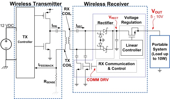
Fig. 1: Typical wireless power system architecture diagram
Reference [2] offers a more detailed introduction to the basic concepts of wireless power, while references [3 to 6] provide additional system design guidelines for wireless power implementations.
To extend power capability to 10 W, several additional points must be considered. First, the silicon power components must be designed to handle the peak and continuous power levels required. On the transmitter side, the power FET components are external to the transmit controller, so they can be scaled up as needed to handle the peak currents. On the receiver side where a physically small solution size is important, integrated FET devices are used to provide a single-chip implementation. The FETs in the RX controller have reduced RDS(on) (relative to the previous 5-W receivers) in order to provide high efficiency and improve thermal performance. The magnetic components (TX coil and RX coil) also must be rated to handle the higher peak currents needed for 10-W power transmission. Finally, as the magnetic field strength is higher for a 10 W system, the receiver side shielding needs to be extended (compared to a 5 W system). This is needed to provide better shielding for the metal components in the system, minimize “friendly metal” losses on the receiver side, and maximize system efficiency.
Referring back to Fig. 1, note that the RX controller provides feedback to the TX controller, asking the TX to vary its output power as needed based on varying load conditions (and coil alignment / coupling efficiency). A common approach to vary the output power is by exciting the TX coil with a constant amplitude / variable frequency ac-signal. An alternate method is to have variable-amplitude / fixed-frequency excitation.
Variable frequency control eliminates the need for an adjustable pre-regulation stage on the TX side, and relies on the resonant tuning of the TX/RX tank circuits. When the TX operating frequency approaches the resonant point, the maximum possible power is transferred from the TX to the RX. To reduce the power delivered to the RX side, the TX controller increases its frequency away from the resonant peak. Now at lighter loads (when the RX needs less power) the TX frequency tends to increase. However, this approach makes the power delivery / control process very dependent on coil tuning. A variable-frequency architecture also may present some challenges in controlling electromagnetic interference (EMI) when used at higher power levels.
The 10-W transmitter system operates at fixed frequency, but uses an adjustable pre-regulator to vary the dc-rail used for coil excitation. A full-bridge circuit is used to generate an AC excitation for the TX coil. The basic block diagram of a fixed-frequency (10 W) wireless power transmitter system is shown in Fig. 2 . When the RX requires more output power, the dc-rail to the voltage to the TX coil power stage is increased. The DC rail voltage is decreased as the RX load goes down.
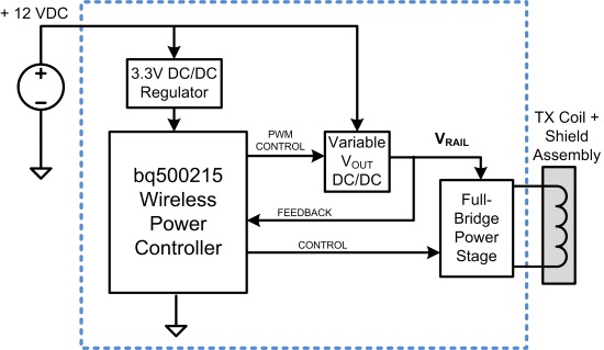
Fig. 2: A 10-W wireless power transmitter with a wireless digital controller
Adjustable output voltage and thermal performance of a 10-W system
The first-generation 5-W wireless power systems typically produced a fixed 5-V output voltage at the receiver side. This was adequate to charge a single-cell Li-ion battery at charge rates in the range of 1 A, and was essentially similar to the ubiquitous USB-type power sources. However, as battery capacities for portable devices increase, higher currents are required to maintain fast charge time.
The bq51025 10 W wireless receiver output voltage can be adjusted with external feedback resistors across the 5 to 10-V range. This allows charging of either one- or two-series cell configurations, and can maintain high efficiency for the one-cell case when combined with a wide input voltage range switch-mode NVDC type of charger [7] . The NVDC charger architecture allows efficient charging of low-voltage batteries while reducing the input current required from a higher-voltage source (such as the wireless RX output). Figure 3 shows the thermal response of the wireless receiver board at 5-, 7-, and 10-V output settings (Fig. 3a, b and c, respectively) while delivering 10-W power to a load. Clearly, the 10-V output condition results in the least amount of heat generated, and should be used if a high-efficiency switch-mode converter is available for battery charging.

Fig. 3: Thermal measurement of the wireless receiver at 10-W load conditions.
The series resonant capacitor (C1 in Fig. 4 ) on the receiver circuit is also critical to optimize thermal performance. In practice, multiple parallel capacitors are implemented to provide the total capacitance needed.
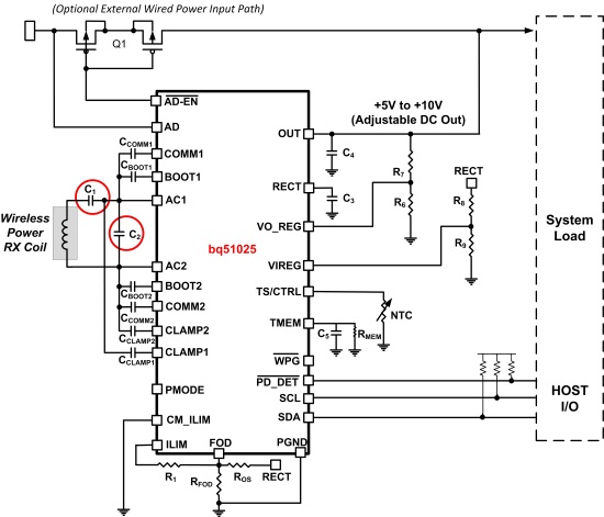
Fig. 4: A wireless power receiver and critical resonant capacitors
The difference in thermal performance using C0G (larger package, low-ESR) and X7R (smaller package, higher ESR) is substantial (Fig. 5 ) .
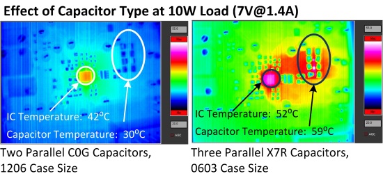
Fig. 5: Effect of capacitors on thermal performance
Smaller, high-ESR capacitors can become the hottest part of the RX PCB. The increase in PCB temperature due to these capacitors limits the ability of the PCB to dissipate heat generated in the IC itself, which means that both the IC and PCB temperatures overall are increased. Total efficiency drops from 80 to 74 percent due to the smaller resonant capacitors.
Figure 6 illustrates the total system efficiency of 10-W wireless power delivery using a wireless power transmitter (bq500215) combined with a wireless power receiver (bq51025), evaluation boards (EVMs), and proper component selection.
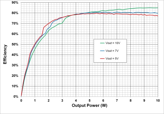
Fig. 6: End-to-end efficiency of 10 W power system for 5-, 7-, and 10-V output settings
Coil selection guidelines
The bq500215 transmitter evaluation module uses a WPC type 29, 10 µH, 30 mΩ coil with a rated current of 9 A [8] This coil ensures compatibility with legacy 5W WPC type receivers, in addition to a 10-W receiver.
For the receiver side, the coil specifications should be optimized to match the application’s target output voltage. In the case where a 5-V output is desired, the RX coil should be in the range of 10 µH for its nominal inductance; for higher output voltages such as 7 or 10 V, the RX coil should be in the range of 15 µH.
While it is ideal to minimize the dc resistance (DCR) of the coils, in the case of the higher output voltage, the DCR can be allowed to increase slightly due to the lower current. Two representative RX side coils are illustrated in Fig. 7 . All RX and TX coil assemblies require back-side shielding material.
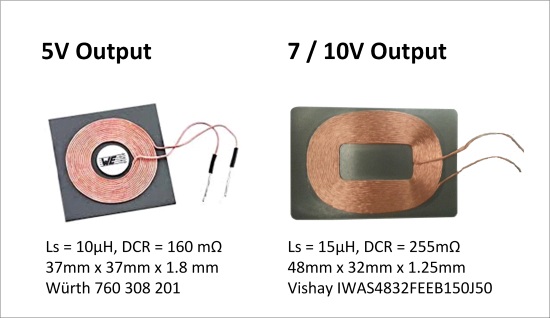
Fig. 7: Typical RX coil specs for 5-, 7, and 10-V output requirements
Battery charging time comparison
Ultimately, the reason to implement a 10 W wireless power system is to reduce the charge time for high-capacity batteries. Figure 8 shows the charge time for a 3.1-Ah Li-ion battery using both 5- and 10-W wireless power systems (in combination with the bq24261 NVDC switch-mode charger). Charge time is substantially reduced — from nearly four hours with the 5-W charger to less than three hours with the 10-W charger. Due to the tapering “top off” nature of the Li-ion battery charge algorithm, total charge time reduction is not directly proportional to the power available. However, the transition point from constant-current to constant-voltage mode, which represents approximately 70 percent of the full charge, is reduced by half (Fig. 8).
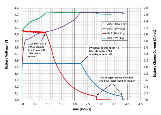
Fig. 8: Battery charge time reduction with 10 W wireless power system
There are many additional details to be considered in the design of a complete 10W power system. References [9 – 10] offer complete guidelines and design calculations required to implement a system using TI’s 10 W Wireless Power Solution.
References
- Wireless Power Consortium Standards
- Sengupta & Johns, “Universally Compatible Wireless Power Using the Qi Protocol,” Low-Power Design
- Tahar Allag, “Test and Troubleshoot a Wireless Power Receiver,” Application Report (SLUA724), Texas Instruments, August 2014
- Johns, Antonacci, and Siddabatula, “Designing a Qi-compliant receiver coil for wireless power systems,” Analog Applications Journal (SLYT479), Texas Instruments, 3Q 2012
- Tahar Allag, “Layout Guidelines for Wireless Power Receiver,” Application Report (SLUA710), Texas Instruments, June 2014
- Ilya Kovarik, “Building a Wireless Power Transmitter
- Jing Ye, “NVDC Charging Design Considerations and Trade-offs” Video Tutorial
- Würth Elektronik (http://katalog.we-online.de/pbs/datasheet/760308141.pdf)
- Norelis Medina, 10W wireless power system video demonstration
- Download these datasheets: bq500215, bq51025, bq24261
About the Authors
Norelis Medina is a systems engineer for the Wireless and Low-Power Chargers group at Texas Instruments where she is responsible for the definition of wireless power solutions and provides support to customers. Norelis started her career at TI in 2004 as an analog design engineer designing power modules for mobile application power management ICs. She graduated from the University of Puerto Rico at Mayaguez with a BSEE, and holds a MSEE degree from Texas Tech University.
Upal Sengupta is an applications manager with the Texas Instruments Power / Battery Management Solutions group. Upal joined TI in 2004 as a Field Applications Engineer and has since worked in various applications and marketing roles for TI’s power management businesses. Prior to that, he gained his background in the portable power field by working as a system design engineer developing mobile phones, portable computers, and consumer battery charger products. He received a BSEE from the University of Illinois, and an MSEE from Michigan State University. For questions about this article, Upal can be contacted at .
Advertisement
Learn more about Texas Instruments


