Introduction
As the latest and greatest gaming systems debut every few years, my stockpile of old video game controllers grows at the same pace. Many of the older game consoles were designed with nonstandard proprietary connectors. Sadly, this means that, even though they are still fully functional, most of my old game controllers are doomed to collecting dust on the shelf. However, with just a little modification, these controllers can be given new life and repurposed to serve as a nifty interface with modern computers. The know-how to make a USB mouse or keyboard out of old components and spare parts can be both a fun and informative way to add functionality to any embedded system with user-control inputs.
Examine Your Old Controller
The basic requirements to make a USB mouse are simple. The mouse needs two buttons for left and right click, and a means to control horizontal and vertical movement.
These essential criteria have been implemented in various ways with differing components and complexity. Gamepads from the 1980s and early 1990s used simple pushbuttons connected to an 8-bit or 16-bit latch. Latching the data every few milliseconds, the game console could easily clock out and interpret which buttons were pressed. Later generations of controllers integrated analog-to-digital converters (ADCs) to sense how far a joystick was moved from its resting position, thus allowing for different movement speeds instead of the “on-off” control of a simple button. More modern controllers even integrated an accelerometer, which gives the user greater variety of control through body movement. Regardless of the controller that you want to use, there should be plenty of information on the Internet about how its data is encoded. Once you get a grasp of how the game controller collects and stores the inputs, formatting the data for USB is the next step.
Make the Mouse
USB is an extremely versatile protocol, and the host system must be ready to accept a wide variety of data packets from whatever device is connected. When the end device is first attached, it must describe its identity, capabilities, and expected data format to the host in a process called “enumeration.” Luckily, most host systems have built-in drivers for commonly used device classes (think flash drives, keyboards, printers, etc.). If an end device enumerates in a certain class, the host computer can use the device without any additional software. A mouse falls into the Human Interface Devices (HID) class, so enumerating under this class will make our mouse plug and play.
When a device first attaches to a USB port, the host sends SETUP data to give the device a chance to enumerate. The end device must decode the SETUP packets and send the device descriptor, followed by its configuration, interface, class, endpoint, and report descriptors. Descriptors are table data that contain detailed information about device operation. Everything from device manufacturer, data buffer size, and communication speed to power consumption and data format is reported in the various descriptors during enumeration.
The report descriptor controls how the computer receives and interprets the data sent over USB. We can identify the left-click and right-click features of the mouse according to the predefined usages in the HID class. The two buttons in our controller correspond to two inputs, each of 1 bit size and each with a logical value of 0 or 1.
USAGE_PAGE (Button)
USAGE_MINIMUM (Button 1)
USAGE_MAXIMUM (Button 2)
LOGICAL_MINIMUM (0)
LOGICAL_MAXIMUM (1)
REPORT_COUNT (2)
REPORT_SIZE (1)
INPUT (Data, Var, Abs)
Since we are only using 2 bits of the data byte, we need another report size of 6 bits that the computer interprets as constants. Note that we do not include any usages for these latter bits.
REPORT_COUNT(1)
REPORT_SIZE(6)
INPUT (Cnst, Var, Abs)
The next 2 bytes that we send correspond to the x-axis and y-axis data, respectively. The data for each direction has its own report size of 8 bits, and can have a logical value in the range of -127 to 127 for an 8-bit signed integer.
USAGE_PAGE (Generic Desktop)
USAGE (X)
USAGE(Y)
LOGICAL_MINIMUM (-127)
LOGICAL_MAXIMUM (127)
REPORT_SIZE (8)
REPORT_COUNT (2)
INPUT (Data, Var, Rel)
Since each line of the report descriptor above has a predefined value in the HID Usage Tables (http://www.usb.org/developers/devclass_docs/Hut1_11.pdf ), the following array represents the total report descriptor for our mouse example.
unsigned char RepD[]= // Report descriptor
{
0x05, 0x01, // USAGE_PAGE (Generic Desktop)
0x09, 0x02, // USAGE (Mouse)
0xA1, 0x01, // COLLECTION (Application)
0x09, 0x01, // USAGE (Pointer)
0xA1, 0x00, // COLLECTION (Physical)
0x05, 0x09, // USAGE_PAGE (Button)
0x19, 0x01, // USAGE_MINIMUM (Button 1)
0x29, 0x02, // USAGE_MAXIMUM (Button 2)
0x15, 0x00, // LOGICAL_MINIMUM (0)
0x25, 0x01, // LOGICAL_MAXIMUM (1)
0x95, 0x02, // REPORT_COUNT (2)
0x75, 0x01, // REPORT_SIZE (1)
0x81, 0x02, // INPUT (Data,Var,Abs)
0x95, 0x01, // REPORT_COUNT (1)
0x75, 0x06, // REPORT_SIZE (6)
0x81, 0x01, // INPUT (Cnst,Var,Abs)
0x05, 0x01, // USAGE_PAGE (Generic Desktop)
0x09, 0x30, // USAGE (X)
0x09, 0x31, // USAGE (Y)
0x15, 0x81, // LOGICAL_MINIMUM (-127)
0x25, 0x7F, // LOGICAL_MAXIMUM (127)
0x75, 0x08, // REPORT_SIZE (8)
0x95, 0x02, // REPORT_COUNT (2)
0x81, 0x06, // INPUT (Data,Var,Rel)
0xC0, // END_COLLECTION
0xC0 // END_COLLECTION
};
So now you ask, what is the actual takeaway from this report descriptor explanation? By using the report descriptor above, all we need to do is format the data from our game controller in the following format (Table 1) and the host system will be able to properly understand the input.
Table 1. USB Mouse Data Format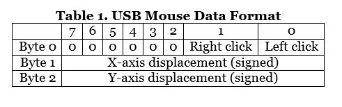 It is important to note that the directional data is both signed and relative to the cursor’s current position. If a -1 is sent as the x-axis displacement, the cursor will move one pixel to the left. A +1 in the x-axis displacement byte moves the cursor one pixel to the right. The same applies to the y-axis, with negative values moving the cursor up and positive values moving the cursor down.
Two different methods for creating a USB interface can now be shown. You can use a MAXQ612/MAXQ622 16-bit microcontroller with built-in USB serial interface engine, or use any microcontroller with a MAX3420E/MAX3421E USB peripheral controller. Figure 1 shows the first implementation. The game controller which I chose has a convenient I2C interface. Using the MAXQ622 to serve as the I2C master interface to communicate with the game controller, parse the data into the format shown in Table 1 above and handle the USB transactions. Now a single-chip mouse solution can be achieved.
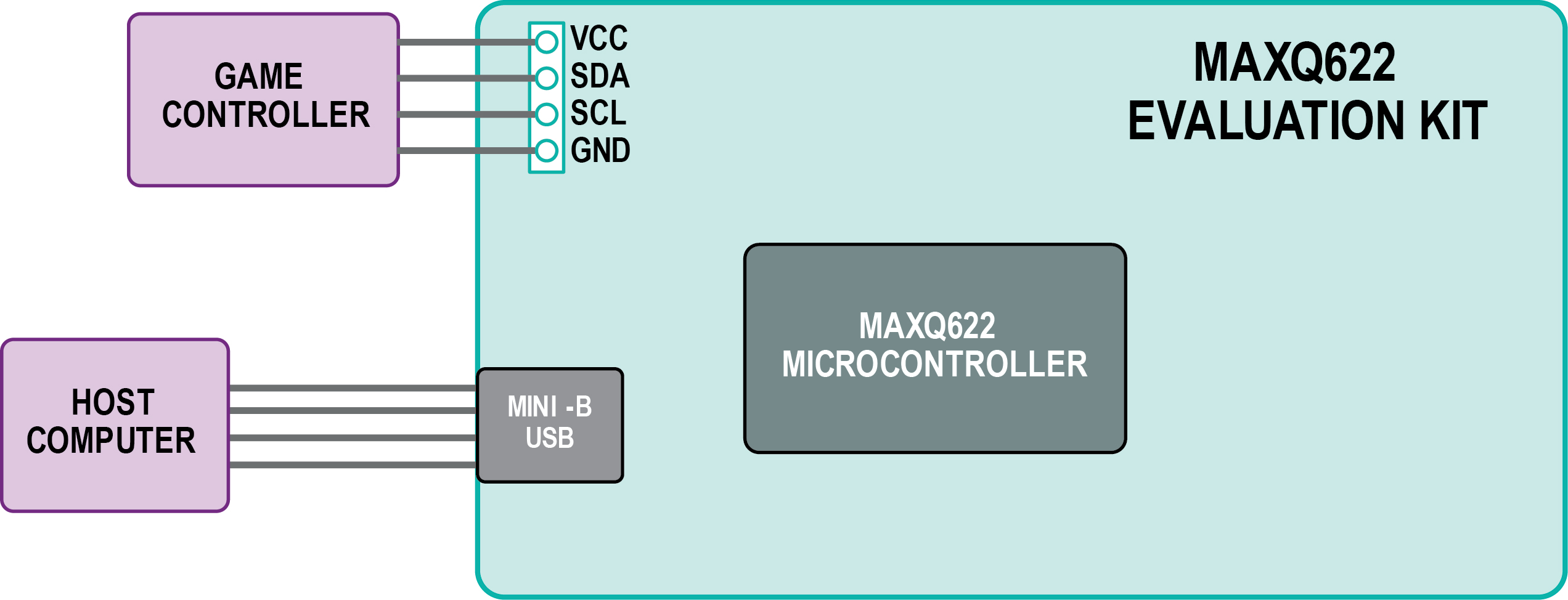
Figure 1. Diagram of a single-chip USB mouse. The MAXQ622 microcontroller and MAXQ622 evaluation (EV) kit are featured in this design.
Other than external bypass capacitors, pullup resistors on the I2C lines, and a crystal oscillator, no additional components are required for this example design.
Figure 2. shows a more generic solution using the MAX3420E USB peripheral controller with any microcontroller equipped with I2C and SPI functions.
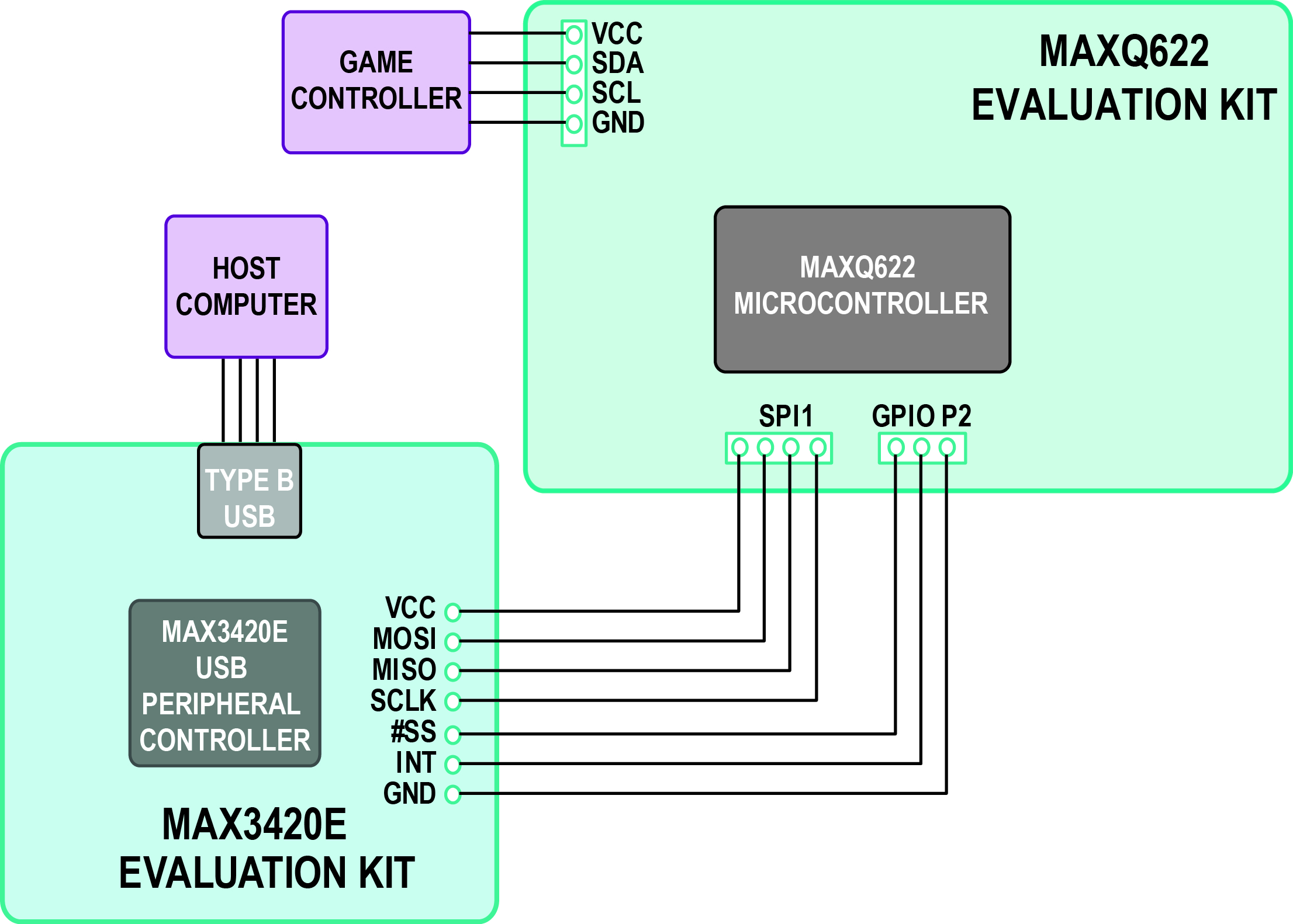
Figure 2. Diagram of a USB mouse, now using the MAX3420E USB peripheral controller and theMAX3420E EV kit. While any microcontroller with I2C and SPI capabilities could be used, in this case we continue to use the MAXQ622.
The MAX3420EEVKIT-2 provides headers for all interface pins, which include the MOSI, MISO, #SS, and SCLK pins for SPI communication and the INT pin to signal interrupts to the microcontroller. The MAX3420EEVKIT-2 has an on-board Atmel® ATtiny2313 microcontroller that, with custom firmware, could implement a bit-banged I2C bus to directly interface to the game controller. In this example, the MAXQ622 EV kit, which has both I2C and SPI peripherals, was used as the generic microcontroller.
Conclusion
Now you know how to use an old video game controller and any microcontroller with the proper interface to implement a USB mouse. The process is as easy as connecting a few jumpers and downloading the firmware.
The code provided here has several functions. It continually monitors the USB bus for any activity or incoming requests from the host; it periodically polls the game controller for new data, sends this data to the host, and blinks LEDs as status/time indicators. Both implementations are equipped to recognize USB bus resets and USB bus suspend events. Both perform remote wakeup of the host and respond appropriately to all host CONTROL transfers.
Perhaps you want to know more or investigate the possibilities further? You can find more nitty-gritty details about how to handle the USB protocol, in an application note 3690 “USB Enumeration Code (and more) for the MAX3420E,” at http://www.maximintegrated.com/AN3690
Atmel is a registered trademark and registered service mark of Atmel Corporation.
About the Author:
Mohamed Ismail is an applications engineer at Maxim Integrated and specializes in intelligent system design. He joined Maxim in 2013 after getting his MSEE from Stanford University and serving as the Stanford Kyoto Teaching Fellow of electronics in Kyoto, Japan.
Advertisement
Learn more about Electronic Products Magazine


