Abstract: The flow-rate measurement that occurs in a heat meter is critical to the accuracy of the energy-measurement requirements of heat-providing utilities around the world. Since all heat meters are essentially integrating flow totalizers, a simulated flow-rate entitlement can provide insight into the trade-offs required to develop a cost-effective flow-rate measurement solution. Because of the effects of flow turbulence and mechanical design limitations in the spool body, the actual flow-rate measurement accuracy is limited and can only approach that of the simulation model with averaging, flow compensation, and multipoint calibration.
Introduction
Simulation and correlation of flow-rate measurement in an ultrasonic heat-meter design is critical to the success of the heat-meter development process. Flow-rate measurement provides the designer with beneficial insight into the entitled accuracy of the heat-meter system measurement electronics, as well as a means of developing the individual product specifications. Without the knowledge of an expected level of performance for the electronic system used to measure the time-of-flight acoustic path in the meter spool body, the designer would be only guessing at the potential performance limits of the design. The principle of simulated time-of-flight acoustic path measurement, and then the corresponding confirmation of such simulation using actual flow-rate measurements from the meter spool body are presented in this short article.
Ultrasonic Time-of-Flight Flow-Measurement Principle
A typical ultrasonic time-of-flight heat-meter spool body is depicted below in Figure 1.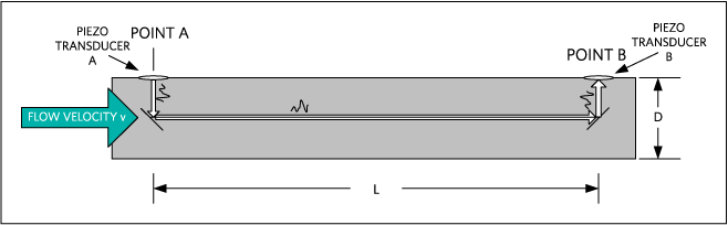
The dimensions L and D are unique for every pipe size. The arrangement of the reflector surfaces within the flow spool body is also unique to every meter manufacturer. Consequently, the ultrasonic time-of-flight principle is based upon the time-of-flight of an acoustic signal in the water. The upstream time-of-flight is longer than the downstream time-of-flight, since the water velocity aids the acoustic signal in the downstream direction and impedes the acoustic signal in the upstream direction. This difference in time-of-flight can be exploited to determine the velocity of the flowing water.
The acoustic time-of-flight of an ultrasonic signal in the downstream direction is: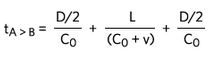
The acoustic time-of-flight of an ultrasonic signal in the upstream direction is: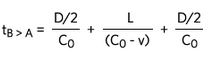
where:
CO is the speed of sound in water
v is the velocity of the water
Subtracting Equation 2 from Equation 1 and simplifying the results, followed then by solving for v, yields the velocity of the water: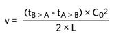
The volumetric flow of the water is then simply calculated with knowledge of the cross-sectional area of the flow diameter of the spool body: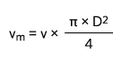
This volumetric flow-rate measurement is the basis for determining the flow rate in a heat-meter system.
Flow-Rate Simulation of the Typical Ultrasonic Time-of-Flight Heat Meter
Using a spreadsheet, the time-of-flight can be calculated and then converted to a volumetric flow rate using Equations 1 through 4. By simulating the time-to-digital converter electronics error of the time-of-flight measurement of the acoustic wave, plots of the entitled accuracy of the system can be created. Note that Equation 3 shows a dependency on the speed of sound in water, where C_Ois dependent upon the temperature of the water. Accurate temperature measurement of the water flow is needed by the heat meter so it can compute the energy consumed. If we assume that the water temperature is +70°C and can be measured accurately, the plot for the simulated flow rate for the typical ultrasonic time-of-flight heat meter shown above is depicted in Figure 2.
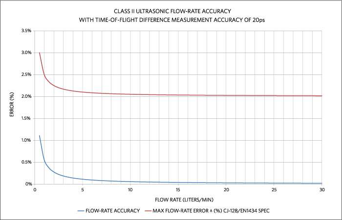 Figure 2. Simulated flow-rate accuracy of the typical ultrasonic time-of-flight heat-meter spool bod y.
Notice from the plot of Figure 2 that the simulated flow-rate accuracy with 20ps of time-of-flight error measurement contributed by the time-to-digital converter exceeds the specification error bars by a significant margin. This simulation depicts the entitled flow-rate accuracy without the effects of flow turbulence and mechanical design limitations in the spool body. Any additional error in the system would add to the error shown in this plot. The main sources of that additional error include the effects of flow turbulence and mechanical design limitations in the spool body. The actual flow-rate measurement accuracy is limited and can only approach that of the simulation model with sample averaging, totalizing, and multipoint flow calibration.
Flow-Rate Correlation of the Typical Ultrasonic Time-of-Flight Heat Meter
The typical ultrasonic time-of-flight heat meter is then connected to a water-flow system so that the time-to-digital converter electronics can actually measure flow rate through the meter spool body. Raw flow-rate data can be taken and this raw data is depicted in Figure 3. The plot represents a data set that comprises multiple samples taken at fixed flow-rate intervals. Each flow-rate interval is sampled 50 times to obtain a statistical distribution of the measurement error in the spool body. Notice that this plot is focused on the low-rate region from 0 to 10 liters per minute. The error that is revealed by this plot is sourced from the effects of flow turbulence and mechanical design limitations in the spool body. The accuracy of the time-to-digital converter electronics is not a contributing factor to this error.
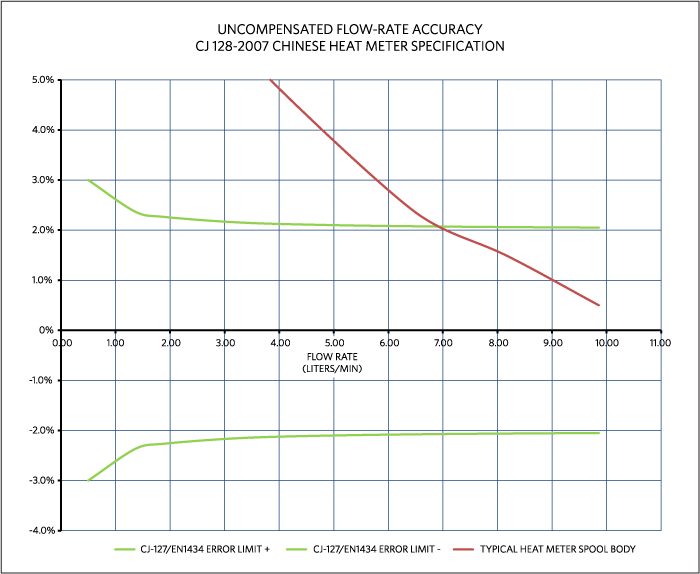
Figure 3. Uncompensated flow-rate accuracy for the typical ultrasonic time-of-flight heat-meter spool body.
The accuracy of the plot of Figure 3 can be increased by applying a typical multipoint compensation curve to the raw data. The data needed to produce the compensation curve is gathered from a highly accurate flow-rate reference. The National Institute of Standards and Technology (NIST) in the United States uses a gravimetric reference system. This is a weigh system with collection tank and a flow-diverting device. This device is the part of the calibration system that directs the flowing water into the collection tank while triggering a clock to determine the collection time. The water collected can be determined in terms of volumetric or gravimetric units. More information on this method of calibration is available for download. The calibration technique used for the set of measurements taken to obtain the multipoint compensation curve is based upon a reference flow meter that is traceable to this NIST gravimetric reference system.
Calibration of each meter is unique, and usually performed by the meter manufacturer before shipment to the end customer. A 10-point compensation curve is applied to the plot of Figure 3 to yield the plot of Figure 4. Notice in Figure 4 that the flow-rate accuracy is better than ±1% down to 0.5 liters per minute of flow rate. By comparing the plot of Figure 4 to the plot of Figure 2, it can be seen that the accuracy of the meter can be made to reflect the accuracy of the time-to-digital converter electronics.
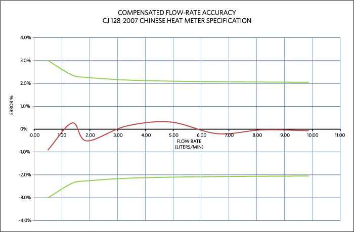 Figure 4.Compensated flow-rate accuracy for the typical ultrasonic time-of-flight heat-meter spool body.
Conclusion
Simulation of a heat-meter system is a powerful tool to enable the heat-meter designer to accurately predict the behavior of the spool body mechanical design. The type of simulation shown here provides insight into the entitled accuracy of the heat-meter system measurement electronics. The accuracy of the typical ultrasonic time-of-flight heat meter is dependent upon many variables, including the effects of flow turbulence, mechanical design limitations in the spool body, sampling rate, and the accuracy of the time-of-flight measurement itself. If the accuracy of the measurement electronics of the heat-meter system is sufficient, then this variable can be made noncritical, and the overall meter accuracy can be compensated to meet the required specifications. The 10-point compensation method described is a very common method of calibration deployed by all heat-meter manufacturers.
Advertisement
Learn more about Maxim Integrated


