Stepper motors are impressive little engines that may not be getting the credit they deserve, as they are a relatively important part of our electronic lives. Printers and CNC machines are mass-produced products we take for granted that employ stepper motors to do our work. The vast majority of the public may not even know they exist; so we’re going to take a brief look into what types of stepper motors there are, how they work, and why we use them.
How do they work?
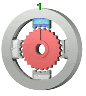
Stepper motors are DC charged coils arranged in a circle into what’s called an “array.” As each “phase” or coil in the array is energized, it rotates the motor. Each small rotation is referred to as a step, which is where the name, stepper motor derives from, and each has its own characteristics, such as size and number of phases.

Controlling these fascinating little machines is a bit more involved than your run-of-the-mill DC motor. Since each design has been uniquely adapted to the task it’s assigned to do, there are some equally unique electronics that control them.
What types are there?
There are three different types of stepper motors currently employed: Unipolar, Bipolar, and Variable reluctance. Since the two most popular are Unipolar and Bipolar we’ll turn most of our attention to those types.

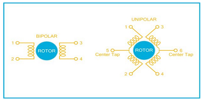
Unipolar stepper motors feature one coil per phase and anywhere from five to eight wire leads. When these wires are connected to transistors, they allow the coils to be fired in a particular order. The direction the motor turns is dependent on the firing order of the coils. A downside to such a design is that only one coil at a time can be charged, thus resulting in a limited torque holding capacity.
Bipolar stepper motors typically have only four wires sprouting from their base, but since only one coil per phase is activated, the current needs to be reversed to step the motor. Due to the need to reverse the current, we can’t use traditional transistors to control the phases. To control the coils, you will need an H-Bridge circuit, which allows a voltage to be applied across a load in either direction. An advantage of this design is that it’s stronger compared to a similarly sized Unipolar motor.
A Variable Reluctance Motor features a non-magnetic rotor at its core, where greater resolution is achieved if more teeth are added. The winding energizing sequence is also reversed from permanent magnet motors. Each “step” angle is also half of what they normally are.
Why do we use them?
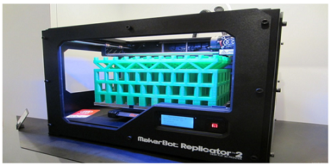
Stepper motors exhibit more torque and precision by design than their standard DC motor counterparts. As mentioned above, the color printer is a great example of a stepper motor’s use, where it has the ability to keep rolling paper in lock-step with the ink mechanism. The devices also give CNC machines and 3D printers their almost infinitely controllable precision.

Drawbacks
As with most innovations, stepper motors have their limitations, one being its high speed torque ability. These motors aren’t very efficient, draw the most load when they’re not actually working, and tend to run a little hot. The Stepper also lacks feedback in relation to position, and running what’s called an “open loop” may help solve this problem.
Next time you print something at work or create that crazy toy on your 3D printer, you’ll have a new appreciation for how they do it.
Sources: instructables.com, learn.adafruit.com
Advertisement


