A close look at the USB Type-C orientation-independent connector with a 24-pin signal plan through which it can deliver up to 10 Gbit/s, draw or supply up to 100 W, and cater to alternate high-speed signaling protocols.
The USB Type-C connector is set to become universally applied due to its sleek design and robustness, its reversible plug orientation and cable direction, and of course its scalable power and performance.
For end users, this promises to put an end to the rats’ nests of different cables and scrambling in the dark for the right connector end and orientation. For designers, this reduces the likelihood of a broken connector receptacle turning their system into a paperweight, but requires some front-end redesign, both electrically and physically.
In this, the first of a series devoted to USB Type-C, we will look at the impetus behind the standard, and the basic signal plan.
The Type-C connector derived from a recognition that USB needed to adapt to serve smaller, thinner and lighter form-factors and that usability and robustness requirements have advanced beyond the ability of current USB connectors. The new design was guided by the principles that it would enable new and exciting host and device form-factors where size, industrial design and style are important parameters; work seamlessly with existing USB host and device silicon; and enhance ease of use for connecting USB devices – with a focus on minimizing user confusion for plug and cable orientation.

Photo: USB Type-C receptacle interface (front view) showing all 24 signal lines. CC1 and CC2, as well as SBU1 and SBU2 are the pins that provide many of the new features that make Type-C special. Image Courtesy of Keysight Technologies
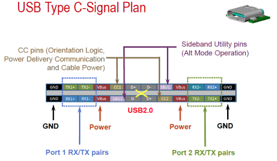
The connector’s 24-pin signal plan is as shown in the Figure. Four pins are dedicated to ground (GND) and four to power (VBUS). These eight mate first upon insertion, followed by the data pins for USB 3.1 and USB 2.0. Type-C connectors are capable of delivering deliver up 5 A @ 20 V using USB Power Delivery (PD), but USB Type-C Current only mandates 1.5 and 3 A at 5 V.
The Port 1 and Port 2 RX/TX differential pairs are for USB 3.1 SuperSpeed (10 Gbits/s), while USB 2.0 signals (480 Mbits/s) are carried over the center D+/D- pairs. The USB 2.0 pins support all three modes, LS, FS, and HS and both the USB 2.0 and USB 3.1 specifications define all the characteristics, enumeration, protocol and management features for the respective interfaces.
The transmitter pins on the host, or Downstream Facing Port, (DFP) are routed to the receiver pins on the Upstream Facing Port (UFP) of a USB port operating as a device. The DFP-to-UFP connection is managed and maintained using the two Configuration Channel (CC) pins.
The CC pins detect attachment; feed the orientation logic that establishes bus routing; establish DFP-UFP roles; discover and configure VBUS USB Type-C Current modes or USB Power Delivery; and also configure VCONN. We’ll have more on current modes, power delivery and VCONN in a later installment.
Finally, there are the Sideband Use pins (SBU 1 and 2). These are used to carry the very important Alternate Modes that allow the Type-C connector to transport other high-speed protocols, such as DisplayPort. They also support the Audio Accessory Mode.
As default, SUB1 and SBU2 are either open circuit or have a weak pull-down to ground and are pre-wired in a the standard USB Full-Featured Type-C cable as single-ended wires (SBU_A and SUB_B).
The mechanical structure, power modes, Alternate Mode, VCONN, orientation detection, the various cable assemblies and testing Type-C connectors are but some of the topics we will address next.
Advertisement
Learn more about Electronic Products Magazine


