Planar transformers have been around for many years, and I have often wondered why they are not used more frequently. These usually SMT devices have a distinct density advantage and a high-frequency loss advantage.
Switching power conversion is often done at 200 KHz or higher — with quite a few designs above 1 MHz. Planar magnetics have demonstrated that their flat, wide conductors will decrease skin and proximity losses in windings compared to round wire, along with having much lower leakage inductance. Implementing the coil in a multi-layer PCB is easier than winding wire around a core. Also, planar magnetics can have very good thermal performance because of greater surface area to volume ratio — providing more area to contact a heatsink.

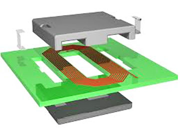
Fig. 1: A PCB design planar power transformer.
There are a few downsides. While planar format is usually more compact, it often results in a larger PCB footprint. The format allows windings to be placed closely together, thus reducing leakage inductance, but this will usually increase parasitic capacitances. The winding configurations commonly employed in planar devices are advantageous in reducing AC winding losses. However, in inductors and flyback transformers that use gapped core center legs, the winding configuration can result in greater AC losses.
The repeatability of characteristics can be compromised due to the somewhat complex final assembly of PCB windings and core material. Also, a greater portion of the winding window is filled with dielectric materials, thus reducing the window utilization factor (often 0.25−0.3, compared to 0.4 for conventional magnetics).
There are two kind of planar transformers — those built into a PCB design and a purchased unit offering most of the same advantages. The purchased unit will have a taller profile (with no PCB bottom side core material) but will still be lower-profile than most conventional wound core devices. These purchased devices are often tuned and optimized to the particular type of power converter, switching frequency, and conversion voltage. They can be very cost-effective.
A few excellent examples
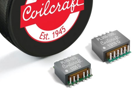
Coilcraft is a leader in this area and has devices with power ratings from 160 to 800 W. For example, their PL160 series is rated for 160 W running at 200 to 700 kHz with a nominal 48-V input. Its size is 20.83 x 23.37 mm with a height of 8.94 to 9.53 mm. The part has 0.229-mm clearance above the seating plane. It comes in five versions with dual primaries and a 4-, 5-, or 6-to-4 turns ratio. An auxiliary primary winding is optional. Primary inductance is 153 to 345 µH and primary DCR is 14.7 to 21.5 Ω, with a volt-time product of 150 to 224 V-µs.

Fig. 2: The Coilcraft PL160 Series.
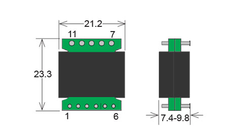
The SX40 series of planar transformers from Standex Meder Electronics are rated for 180−360 W with single (H 7.4 mm) and double (H 9.8 mm) interleave designs. They work best at 100 to 800 KHz and have a leakage inductance of just 0.1 to 0.4 µH. The devices come in 22 styles (x2) with three different winding layouts and primary inductances of 117−345 μH.

Fig 3: Standex Meders SX40 series.
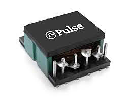
Pulse Electronics offers the PH0910.003CNL high-frequency flat coil planar transformer with a 300-W power rating, 27.0 x 30.5-mm footprint, and a 12.1-mm height. Frequency range is 200 to 700 KHz and isolation is 1500 Vdc.

Fig. 4: The Pulse PH0910.
The parts have three primaries with a ratio of 7/7/3 to 4, and the secondary has three taps. Leakage inductance is 1 µH max. and primary inductance is 588 µH min.
Advertisement
Learn more about CoilcraftPulse ElectronicsStandex-Meder Electronics


