Many applications require communication between various sensors and a central controller for processing and analysis. To maintain the safety mandated to the user interface and to prevent transients from being coupled from various sources, galvanic isolation is almost always required. Examples of these systems are precision robotic arms that need to operate within harsh industrial environments or arc welders or patient monitors that need to operate during defibrillation. Other pertinent applications include motor and power control, instrumentation, industrial automation, and healthcare.

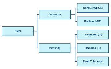
Fig. 1: Types of electromagnetic compatibility (EMC).
A CE mark is usually required to sell products in the EU, and an FCC classification is needed to sell products in the U.S. To obtain these certifications, an electromagnetic compatibility (EMC) test suite must be performed on the system.
Think of keeping the EMC in check as being a good neighbor — not making too much noise and being tolerant when your neighbors make noise. This can be seen in Fig. 1 , in which EMC is categorized into immunity and emissions. Emissions can be further categorized into conducted emissions and radiated emissions. Immunity has the same two versions, plus transient immunity and fault tolerance.
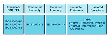
Each category has its own system standards, and compliance is required to achieve a CE mark or FCC classification, as shown in Fig. 2 . In industrial and medical system environments, conducted and radiated emissions typically have to comply with EN55011, EN55022, or FCC Part 15. Conducted immunity must comply with IEC61000-4-6 and radiated immunity must comply with IEC61000-4-3. Transients can be split into three categories: ESD (electrostatic discharge) with standard IEC61000-4-2, EFT (electrical fast transients) with standard IEC61000-4-4, and surge with standard IEC61000-4-5.

Fig. 2: EMC Categories and standards.
Resolving EMC issues after the system is designed can be a challenge because the further along you are with your design, the fewer available techniques there are. Designing for EMC at the start of your project is critical to minimizing the time spent on board iterations and reducing the design time and project cost.
Using digital isolators can be very effective in dealing with EMC transient threats, as galvanic isolation allows for the flow of data while preventing the flow of current. At the same time, the digital isolator should adhere to the good-neighbor rule and not induce noise to upset its neighboring components. Galvanic isolation can be implemented using different coupling elements across the isolation barrier. Traditionally, optical methods were used, but these have been proven to be power-hungry and have a limited lifetime due to the light-emitting source. Digital isolators can be implemented using inductive or capacitive coupling methods with insulation materials, such as polyimide and SiO2, and have the benefit of a longer lifetime and lower power consumption.
Consider two examples from the large number of digital isolators available: Analog Devices’ ADuM1xx and ADuM2xx. These devices implement inductive coupling across the isolation barrier using monolithic air-core-transformer technology and have been proven to be robust against large transient threats. The many versions of these devices include ones with one to five channels and with bi-directional channels.
The devices can pass the required radiated emissions standards while operating at rates from DC to 150 MHz and feature propagation delays as low as 10 ns. They offer immunity against surge transients of up to 16 kVpk and common-mode transient immunity of 100 kV/µs. Supply voltages range from 1.7 to 5.5 V. Quiescent supply current is as low as 2.2 mA, and total dynamic current is 0.03 mA/Mbits/s. Packages are as small as an 8-lead SOIC and pricing as low as $0.88 ea/1,000.
Advertisement
Learn more about Analog Devices


