BY VARUN MERCHANT
Mainstream Technical Marketing Manager
Tektronix
www.tek.com
If the electronic device you are developing plugs into the wall for power, chances are that you will need to send it to a compliance lab to ensure it meets a variety of international standards such as CE, IEC, CEC, CQC, Energy Star, and SPECpower.
Each trip to the compliance lab, depending on the lab’s pricing and the complexity of the required tests and the DUT, will cost anywhere from $2,000 to $5,000. Assuming all goes well, that cost is factored into the development budget and you can schedule testing in advance so you’re not delaying the product release date.
But the situation changes quickly if your design fails compliance testing. First you have to figure out why it failed and devise a fix. Then you have come up with the budget for the re-test and wait several weeks in the compliance lab’s testing queue. You’re adding expense and losing your time-to-market advantage.
Scenarios such as this are a big reason why pre-compliance testing is so important. Done correctly with the right equipment, it can ensure that compliance testing is little more than a formality, saving you time and money.
Given the advantages of pre-compliance testing, why doesn’t everyone do it for every new design, every time? There are two main reasons why engineering teams skip pre-compliance. The first is a lack of in-house power measurement expertise, coupled with concerns about a long learning curve. The second is a lack of cost-effective, easy-to-use power analysis equipment for benchtop use. With the introduction of low-cost power analyzers with built-in pre-compliance testing and reporting, those reasons are now falling by the wayside.
Here we look at using a low-cost power analyzer to assess the compliance of a product’s ac mains current harmonics to the IEC 61000-3-2 standard used in Europe and widely adopted around the world, generally with little to no modifications. This standard sets the limit for equipment that draws input current ≤ 16 A per phase. Equipment that draws >16 A and ≤ 75 A per phase is covered by IEC 61000-3-12. Harmonics measurement and evaluation methods for both of these standards are governed by IEC 61000-4-7.
Current harmonics
Because a switching power supply presents a nonlinear load to the power line, the input voltage and current waveforms are not identical. Current is drawn for some part of the input cycle, causing the generation of harmonics on the input current waveform. Excessive harmonic energy can affect the operation of other equipment connected to the power line and increase the cost of delivering electric power.
Most modern systems have some sort of input power conversion circuitry (Fig. 1) . There’s typically an input rectifier on the input stage followed by a bypass capacitor. Depending on the design, there may or may not be a power factor correction circuit. The input power is influenced by this input circuit and this in turn results in the non-linear response. This leads to a distorted non-sinusoidal waveform on the input current and, ultimately, disruptive harmonics.
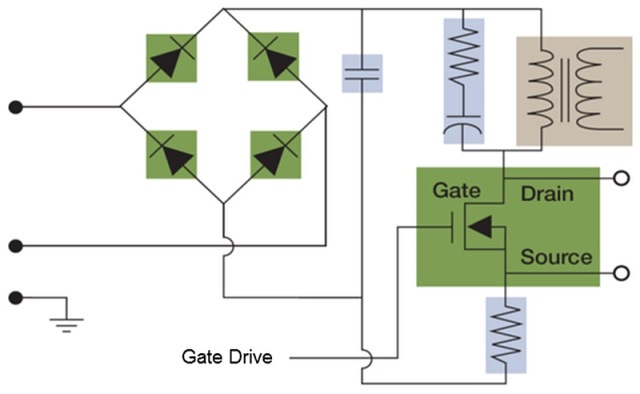
Fig. 1: Typical input power conversion circuitry.
Harmonics can be defined as a series of closed sinusoids with different magnitudes that can be represented as individual multiples of the fundamental signal frequency. The magnitude of each harmonic depends on the distortion of the signal. In other words, harmonics are a mathematical and visual representation of a distorted signal in the form of multiple pure sinusoids such that, if all the sinusoids were added together, you would get the original signal.
Generally speaking, Fourier analysis is used to mathematically calculate harmonics on a given signal. Most measurement instruments use either fast Fourier transform (FFT) or discrete Fourier transform (DFT) algorithms to calculate harmonics. DFT requires more processing power, but can be more accurate. Ideally, you want equipment that uses DFT processing for the highest accuracy possible.
In the real world, device loads are not constant which can lead to changing magnitudes for each harmonic value (Fig. 2 ). Such harmonics are called fluctuating harmonics, and because they are ever-changing, it’s important to quantify them in real time. Fluctuating harmonics can also produce components that are not exact multiples of the fundamental frequency. The components generally lie between the supply harmonics and the interharmonics. The IEC 61000-3-2 standard defines these components at 5 Hz intervals and requires evaluation for final conformance.
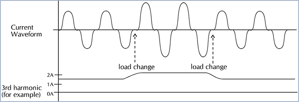
Fig. 2: Ever-changing loads lead to fluctuating harmonics.
IEC 61000-3-2 requirements
Under the IEC 61000-3-2 standard, equipment is grouped into one of four classes. These classes were establish based on a number of factors such as the amount of equipment in use, duration of use, how often the same equipment is to be used in a given time frame, power consumption, and harmonics spectrum, including phase or how clean or distorted the current drawn by the equipment is. Based on these criteria, equipment is classified into the following classes:
- Class A: Balanced three-phase equipment, household appliances, excluding equipment identified by Class D, tools excluding portable tools, dimmers for incandescent lamps, audio equipment, and everything else that is not classified as B, C or D
- Class B: Portable tools, arc welding equipment which is not professional equipment
- Class C: Lighting equipment
- Class D: Personal computers and personal computer monitors, television receivers
The requirements for each class can be very specific. For example, a microwave oven is considered Class A equipment and is tested with 100% nominal power. The oven must be operated with 1,000 grams of water in a glass bowl having a maximum material thickness of 3 mm and an outsider diameter of 190 mm. For pre-compliance testing, it is vitally important to confirm the exact requirements for your particular type of equipment.
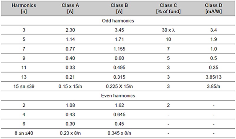
The standard defines the limits for each class to the 40th harmonic order (see Table 1 ). The limits for class A and B are constants and do not depend on fundamental current or power. Class B uses the same limits as Class A multiplied by a factor of 1.5. On the other hand, Class C and D have limits that are either a function of fundamental current or nominal power ratings. Regardless of the class, all the harmonic components should stay within these limits in order to be considered compliant.
Table 1. IEC 61000-3-2 harmonic component limits.
In addition to the defined harmonic component limits, the standard also has requirements for test system accuracy. The ac power source has to be within 2% of target voltage and within 0.5% tolerance for frequency specifications. The standard also states limits for harmonic content and voltage crest factor. For pre-compliance testing, a proper ac source is recommended, but not required. Typically, simply using line power should provide enough information to make the right decisions for a particular design.
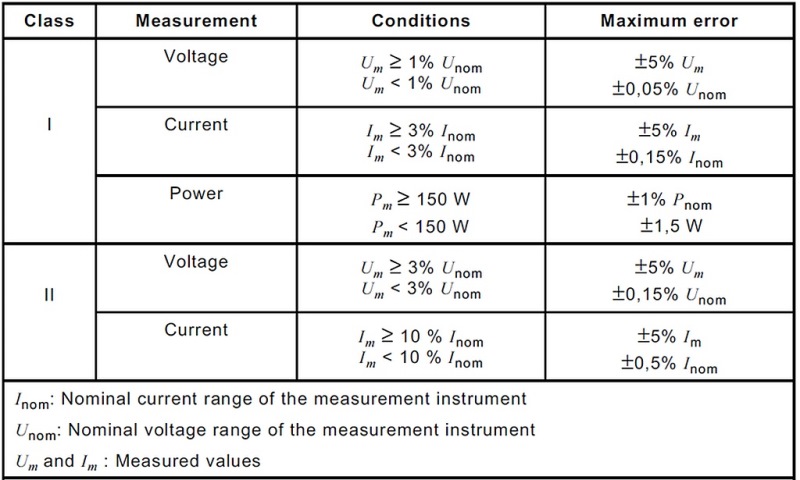
The standard also defines requirements for measurement system accuracy (see Table 2 ). Two classes of equipment are defined. Intended for full compliance testing, Class 1 equipment has tighter accuracy requirements compared to Class 2 which has somewhat relaxed requirements and is intended for general verification and pre-compliance testing. These requirements should be considered when selecting a power analyzer for this application.
Table 2. Measurement system accuracy requirements for power compliance testing.
The standard also describes measurement method requirements. For measuring fluctuating harmonics, the data needs to be captured every 200 ms with no gaps. Each data set should capture either 10 cycles at 50 Hz or 12 cycles at 60 Hz. Each 200-ms block has to be analyzed using DFT to determine the magnitude of the 40 current harmonics. Power software is used to perform this analysis and make the comparison to the specified limits.
The standard also requires checking for interharmonics. For each block of 200 ms, over 400 harmonics from 5 Hz to 2,025 Hz are measured. These components are then presented as 40 harmonics by grouping the 400 together as defined by the standard. For example, in Fig. 3 , the 6th harmonic is a sum total of harmonic energy from 275 Hz to 325 Hz, such that all the energy around that frequency is discovered. This is done for all 40 harmonics.
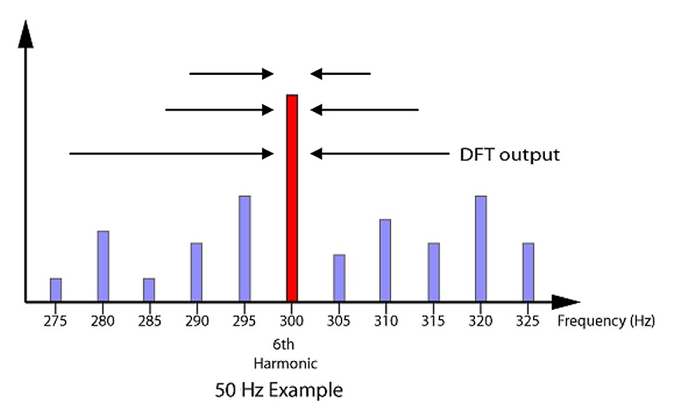
Fig. 3: Method for capturing and representing interharmonics.
In addition to harmonics, frequency, power, power factor, voltage harmonics, and fundamental frequency measurement are also required by the standard. The standard also requires that software used for the test be able to flag overload conditions and gaps in the data.
Pre-compliance testing
When it comes to pre-compliance testing, the best approach is to test early and often throughout the design cycle. In most cases, relatively stable line power and a power analyzer are all that are needed to run pre-compliance tests. A good power analyzer solution may not fully meet all compliance test requirements, but it is significantly more affordable than a higher-end solution and provides a high-degree of confidence that a design will pass during the final compliance test. Equipment intended for pre-compliance applications should comply with nearly all 61000-3-2 requirements, including interharmonics testing, and be designed such that it will never give a false pass; the Tektronix PA1000 power analyzer is an example of such an instrument.
To make the connection between the power analyzer and the device under test, in this case a 1,300-W microwave oven, a breakout box is used (Fig 4 ). From there, it is a simple matter to define test parameters, turn on the microwave, and run the tests.
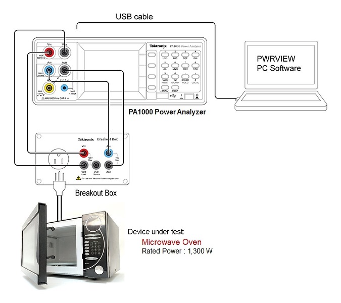
Fig. 4: Set up for pre-compliance testing of a microwave oven.
In the result for one such test (Fig.5 ), you can see that the third harmonic has exceeded the maximum limit; this could be the result of the input power design or some other problem on the input side. Exporting the test results to a .csv file can be helpful to identifying the source of the excessive harmonic energy.
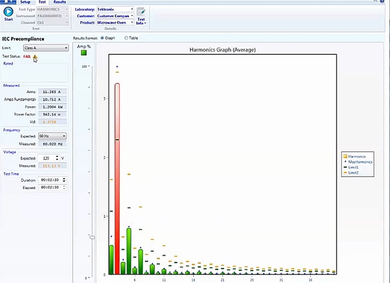
Fig. 5:. Pre-compliance testing quickly shows where a device is exceeding IEC 61000-3-2 limits.
To further enhance your understanding of how power analyzers can be used for pre-compliance testing, these videos demonstrate the use of this instrumentation for various types of power testing.

About the author
As Mainstream Technical Marketing Manager for Tektronix, Varun Merchant supports mid-range wireless and power conversion product offerings. Before joining Tektronix, he worked for several years in product development and design in the semiconductor industry. He holds an MSEE from the University of California, Santa Barbara and an MBA from the Stern School of Business, NYU.
Advertisement
Learn more about Tektronix


