By John Glaser,
Director of Applications Engineering,
Efficient Power Conversion,
www.epc-co.com
One of the key technologies that drove the adoption of electricity as the dominant and most versatile form of energy harnessed by the human race was the transformer. This simple device enabled the efficient conversion of voltages, currents, and impedances, which in turn made practical the electrification of the world and all electrical and electronic devices to follow. Since the early transformers were AC devices, they drove the world towards AC power generation, distribution, and use, despite Thomas Edison and his best efforts to promote DC over AC [1].
However, today we live in an electronic world, and a digital electronic one at that. This digital electronic world is a DC world. This world is enabled by switch-mode power electronics, which provides the same benefits as the original AC transformer to the DC world, as well as new ones like regulation and control. However, there is a particular incarnation of a DC-DC converter that is very true to its AC transformer ancestor, namely the DC transformer, often referred to by DCX [2]. The term DCX typically refers to an unregulated DC-DC converter that converts voltage and current with a fixed conversion ratio, just like an AC transformer. The DCX is especially useful in distributed DC power systems found in data centers and compute farms.
In this article, we see how the revolution in wide bandgap semiconductors, in the form of eGaN FETs, enables a leap in DCX capability with an example of a 700 W hard-switched 4:1 DCX with a 48 V nominal input and 12-V output in an 1/8th brick format.
What is a DCX?
A DCX generally consists of an inverter, an AC transformer, and a rectifier, as shown in Fig. 1 . A modern DCX uses semiconductor switches to form the inverter and rectifier, and runs at high frequency to minimize the size of the transformer. If the rectifier is implemented with active switches (synchronous rectifiers or SRs), the DCX can be capable of bi-directional power flow, and the roles of the inverter and rectifier can be exchanged [3]. The switches are controlled in such a manner that the DCX obeys the standard transformer equations as closely as possible, that is;
VIN = NVOUT
NIIN = IOUT
Note that a DCX does not provide regulation as part of normal operation. This allows the circuit to be highly optimized for maximum efficiency and power density. A modern DCX is often expected to provide some additional features, which may include overcurrent detection, current limiting, enable/disable power control, and measurement and diagnostic capability.
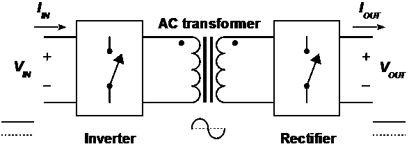
Fig. 1: Block diagram of modern DC transformer (DCX).
There has been a great deal of effort in developing various implementations of the DCX. Some use a variation of the series resonant converter running at or very close to resonance [4], [5]. This has the benefits of soft-switching and inherent transformer-like action while running the inverter and rectifier at fixed duty cycle, but RMS currents are higher than a PWM converter, and implementation of current limiting is a challenge. Another promising approach is the dual-active bridge (DAB) [6], [7]. This approach can make use of soft-switching and still have low RMS currents. However, the DAB does not inherently follow the transformer equations, and thus active control is required at all times.
The simplest DCX is implemented with a standard hard-switched topology, shown in Fig. 2 . The converter operates as a buck converter running at or very close to the maximum possible effective duty cycle D = 1, equivalent to all switches in Fig. 2 running at 50%. This maximizes transformer utilization, and allows the use of a very small inductor value due to the low volt-seconds applied to the inductor. In fact, the inductor is not strictly necessary for ideal DCX operation, but a small inductor allows current limiting when necessary and serves to filter switching spikes and associated ringing.
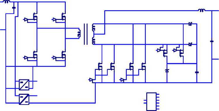
Fig. 2: Isolated hard-switch DCX based on buck converter.
Where is it used?
The typical application of DCX converters is as part of a distributed power system, as shown earlier in Fig. 3 . Such a system only needs close voltage regulation at the load, but the other benefits of a distributed power system, such as high efficiency, increased safety and reduced power bus cost are still desired. The benefits of such systems are well known due to the history of utility power and the widespread use of AC transformers [8].
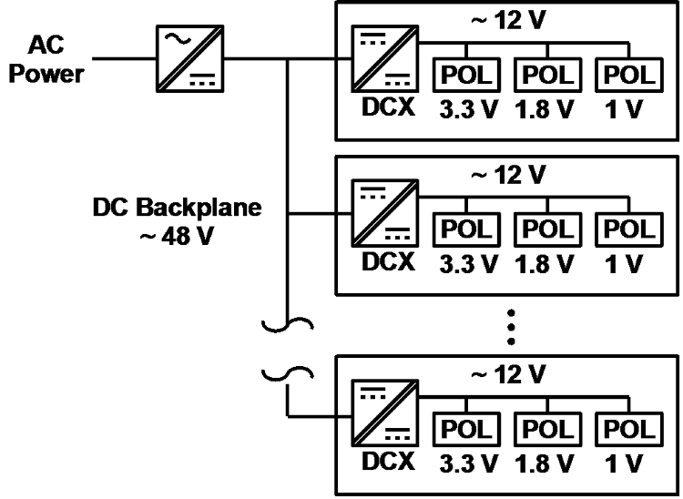
Fig. 3: Typical use of DCX in a distributed DC power system.
eGaN DCX
The superior FOMs for eGaN FETs are well documented [9], and the efficiency gains provided by eGaN FETs have already shown that power density of hard-switched PWM brick-type converters can be increased by nearly 70% [10], [11]. It makes sense to see what kind of performance can be achieved in a DCX converter using eGaN FETs.
Approach
In order to evaluate the performance benefits of eGaN FETs in a DCX converter, it was decided to take the simplest approach possible, namely the use of a standard hard-switched converter (Fig. 2). Since EPC has already designed an eight-brick demonstration board, the EPC9115 500 W 50 V to 12 V nominal, fully regulated bus converter (Fig. 4 ), it made sense to start with this as the baseline design [12]. In order to run as a DCX, only a few simple changes were made. First, the inductor was changed from a 470 nH, 0.9 mΩ molded powder core inductor to a 180 nH, 0.3 mΩ gapped ferrite inductor. Note that running as a DCX would actually allow a smaller-value inductor, but there were no commercially smaller-value inductors with lower DCR that were big enough to connect to the pads on the PCB. Second, the maximum duty cycle clamp was changed in the software from 0.98 to 0.985, to allow a slightly higher output for a given input. Finally, deadtime was decreased from 25 ns to 15 ns.
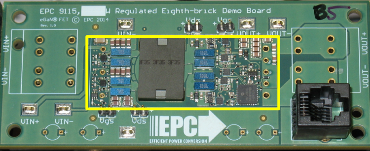
Fig. 4: EPC9115 Eighth-brick demonstration board used as basis for DCX.
Results
The modified EPC9115 converter was tested at three input voltages (48 V, 50 V, 52 V) over a range of load current up to a maximum load current of 62 A. Figure 5 shows efficiency results for the eGaN DCX at 25C (not thermal steady-state). A very flat efficiency curve reaches 97% over a wide range of current for all input voltages, and the output power at 62 A is 710 W for the 48 V input and 771 W for the 52 V input. Worst case efficiency at 62 A load is still 96.6%.
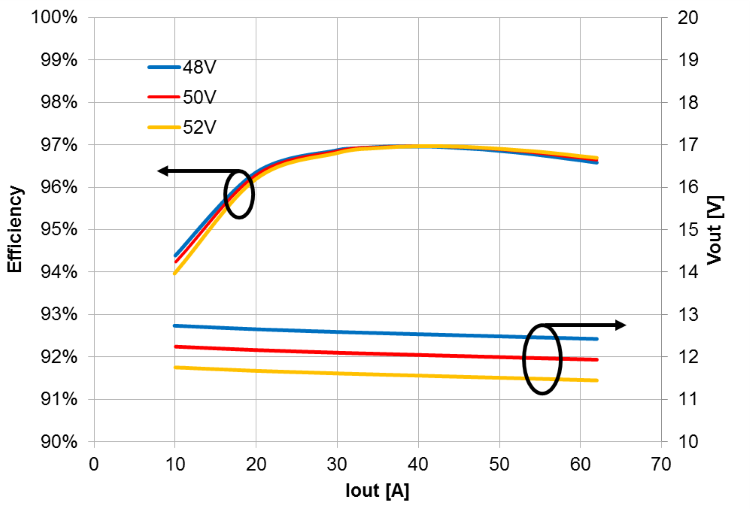
Fig. 5: eGaN DCX efficiency and output voltage for 3 values of VIN (48 V, 50 V, 52 V). Note maximum output current of 62 A, corresponding to 710 W at VIN = 48 V and 771 W at VIN = 52 V.
The results of Fig. 5 are useful for a baseline comparison with other converters, but do not represent a realistic operating condition. Figure 6 shows a thermal image of the converter at thermal steady state with 400 LFM airflow at 24°C, with VIN = 48 V and IOUT = 58.4 A for an output power of 667 W. In this condition, the maximum temperature of 108°C is on the transformer core. The secondary side eGaN FETs are running at 106°C, with the primary side eGaN FETs running at a relatively cool 84°C.
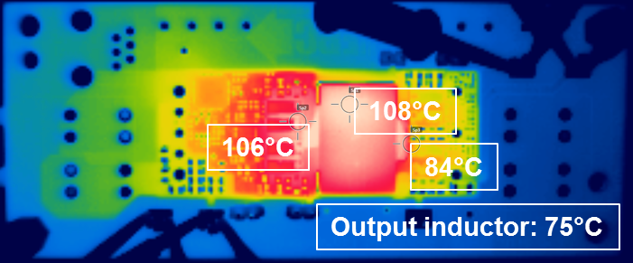
Fig. 6: Thermal image of eGaN DCX with VIN = 48 V. IOUT = 58.4 A and POUT = 667 W, running at thermal steady state with 400 LFM (2 m/s) airflow at 24°C.
What’s next?
The proven efficiency and power density of eGaN FETs in a hard-switching converter far exceeds what is possible with silicon MOSFETs in a similar converter. While it may be possible to achieve similar performance by using silicon MOSFETs in a soft-switched converter, such a design is challenging and has numerous limitations as previously discussed. In addition, it is likely that eGaN FETs will benefit such an approach due to the superior figures of merit.
Note than all testing was done without heat sinks. Most high-power silicon-based brick converters employ an integral heat sink. It’s been shown that the top-side heat removal capability of eGaN FETs can allow up to 30% higher current, hence large improvements could be made [13].
Finally, the DCX performance was evaluated based on modification of the fully regulated EPC9115 eight-brick converter. However, designing a converter as a DCX up front allows many further optimizations, such as control simplification, improvement of the transformer, and using a smaller inductor to shorten the high-current output path. At 60 A, a 1 m resistor dissipates 3.6 W. For A 700W DCX, this is a 10-15% increase in losses for each milliohm. At these high output currents, a key challenge is how to get the current out of such a small converter.
Conclusion
The superior performance of eGaN FETs enable engineering to push the limits of traditional hard-switched DCX performance far beyond what is possible with silicon MOSFETs.
References:
[1] T. S. Reynolds and T. Bernstein, “Edison and ’the chair’,” IEEE Technology and Society Magazine , vol. 8, no. 1, pp. 19–28, Mar. 1989.
[2] R. P. Severns and G. E. Bloom, Modern DC-to-DC Switchmode Power Converter Circuits . Van Nostrand Reinhold, 1985.
[3] R. W. Erickson and D. Maksimovic, Fundamentals of Power Electronics , Second. Springer, 2001, p. 912.
[4] Y. Ren, M. Xu, J. Sun, and F. C. Lee, “A family of high power density unregulated bus converters,” Power Electronics, IEEE Transactions on , vol. 20, no. 5, pp. 1045–1054, 2005.
[5] D. Reusch and J. Strydom, “Evaluation of gallium nitride transistors in high frequency resonant and soft-switching DC-DC converters,” in Applied Power Electronics Conference and Exposition (APEC), 2014 Twenty-Ninth Annual IEEE , 2014, pp. 464–470.
[6] D. Costinett, H. Nguyen, R. Zane, and D. Maksimovic, “GaN-FET based dual active bridge DC-DC converter,” in Applied Power Electronics Conference and Exposition (APEC), 2011 Twenty-Sixth Annual IEEE , 2011, pp. 1425–1432.
[7] M. H. Kheraluwala, “High-power High-frequency Dc-to-dc Converters,” University of Wisconsin, Madison, 1991.
[8] J. W. Coltman, “The transformer [historical overview],” IEEE Industry Applications Magazine , vol. 8, no. 1, pp. 8–15, Jan. 2002.
[9] A. Lidow, J. Strydom, M. de Rooij, and D. Reusch, GaN Transistors for Efficient Power Conversion , 2nd ed. Wiley, 2015.
[10] J. Glaser, J. Strydom, and D. Reusch, “High Power Fully Regulated Eighth-brick DC-DC Converter with GaN FETs,” in PCIM Europe 2015; International Exhibition and Conference for Power Electronics, Intelligent Motion, Renewable Energy and Energy Management; Proceedings of , 2015, pp. 406–413.
[11] D. Reusch and J. Glaser, DC-DC Converter Handbook – A Supplement to GaN Transistors for Efficient Power Conversion , 1st ed. Power Conversion Publications, 2015.
[12] Efficient Power Conversion Corporation, EPC9115 Demonstration Board , (http://epc-co.com/epc/Products/DemoBoards/EPC9115.aspx) 2015.
[13] D. Reusch, J. Strydom, and A. Lidow, “Thermal Evaluation of Chip–Scale Packaged Gallium Nitride Transistors,” in Applied Power Electronics Conference and Exposition (APEC), 2016 IEEE , 2016.
Originally published on Power Electronics News
Advertisement
Learn more about Efficient Power Conversion (EPC)


