BY NORWOOD BROWN
Staff Field Application Engineer, ams
www.ams.com
In some categories of motor drive applications, users have little or no tolerance for unpredictable, uneven, or irregular motor behavior. While this certainly cannot be said of all motor-driven products — electric toothbrushes, for instance, or battery-powered toys maintain a tight focus on bill-of-materials (BoM) cost and will almost always accept a small amount of erratic motor behavior as a reasonable trade-off for minimizing the cost of the motor — other motor drive applications demand a superior level of operation.
Power tools are an example of a product type in which reliable and predictable motor performance is an absolutely essential feature. Consider the potential for injury and/or upset of a user of a power saw that jumped backward or produced a forward “hiccup” motion on start-up — particularly if they had just stalled the tool in the middle of a cut. Equally, the market would quickly reject an electric drill or similar power tool that started up with different torque and/or acceleration during each use.
Manufacturers of such performance-critical motor systems are keenly aware of their users’ requirements, and have typically sought to meet them through the use of brushed DC motors, which offer a proven ability to maintain commutation and full torque at start-up and while managing varying loads. Counting against the brushed DC motor, however, are its relatively low efficiency and the inherent tendency for the brushes to fail before other components due to mechanical wear or chemical contamination.
By contrast, brushless DC (BLDC) motors are greatly superior to brushed DC motors in many respects:
- Efficiency
- Zero electrical wear
- Clean operation
The main challenge for the designer of a BLDC motor control system is that the motor suffers from hiccupping and inconsistent torque and acceleration, when the commutator is forced to operate in the absence of accurate and real-time absolute rotary position data. Absolute position sensing has, in the past, only been available from extremely expensive sensors: The lower-cost sensing solutions suitable for the BoM budgets of most motor system manufacturers have not met this requirement adequately.
In power tools and other performance-critical end products, then, efficient and reliable BLDC motor technology has generally not found favor. This article suggests, however, that power tool manufacturers and others with similar requirements could adopt the BLDC motor by taking advantage of a semiconductor product type — the magnetic position sensor IC — which, along with a simple magnet, provides absolute position data, comes at a low system cost, is easy to assemble into a motor system, and enables a BLDC motor to maintain optimal commutation at all times.
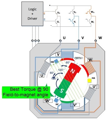
Fig. 1: To maintain maximum torque, the commutator has to maintain a magnetic field through the stators that is orthogonal to the rotor’s magnetic field as the rotor spins.
Position sensor choices for BLDC motor control
A BLDC motor control system has to provide clean start-up operation, maintain continuous commutation, achieve the highest possible efficiency, and extract maximum torque from the available electrical power. The key to achieving all of these goals is knowledge of the position of the rotor relative to the stator, information which enables the motor control system designer to implement a robust electrical drive management solution (seeFig. 1 ).
In particular, the availability of absolute position data enables the motor to start up smoothly from any position. By contrast, a system using discrete sensors or other control technology might perform a jump, or “hiccup,” at start-up in order to calculate its starting position relative to the stators before beginning normal operation. The reduction in torque attributable to inaccurate position data is demonstrated inFig. 2 .
Unfortunately, the simplest and cheapest position-sensing systems available to BLDC motor designers to date have not enabled accurate absolute positioning.
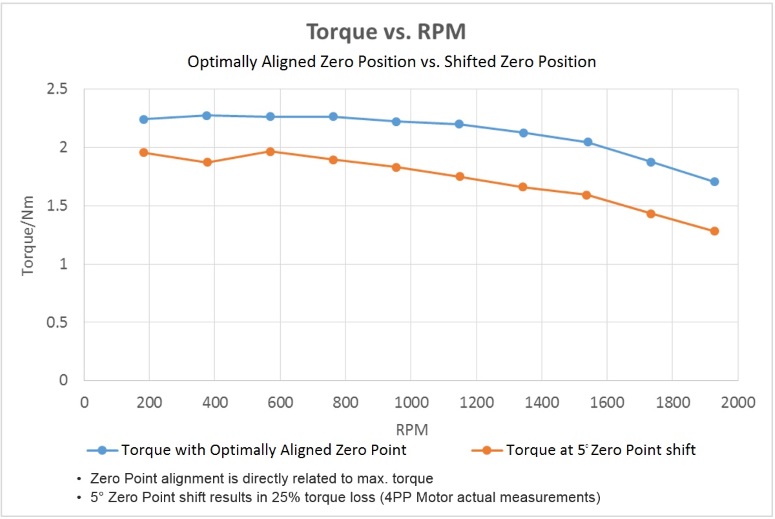
Fig. 2: Reduction in torque attributable to zero-point shift in a four-pole-pair motor.
Back-electromotive force, or back-EMF, position sensing for commutation requires the motor to be in motion in order to induce a magnetic field for sensing. This means that a back-EMF system has no positional data for a static motor unless it has previously been hard-driven to an alignment point — an operation that will result in forward or backward movement of the motor to such an alignment point, independently of the user. And after stalling or jamming, this process must be repeated to enable an orderly re-start. In all cases, until the motor reaches a commutation lock point, it will suffer from reduced torque and delivered power in the absence of data on the absolute rotor/stator positioning.
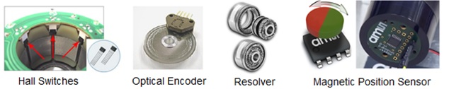
Fig. 3: Hall switches, optical encoders, and resolvers have all been widely used in BLDC motor control systems but are now being superseded by magnetic position-sensing technology.
Discrete Hall switch systems typically consist of three, five, or more Hall sensors fixed in position during the production of the motor (see Fig. 3 ). Errors in placement produce loss of efficiency or power, so extremely precise assembly is required for a discrete Hall sensor system to work effectively. Each Hall sensor also requires its own signal wires, further complicating the production process. What’s worse is that, even though the sensors themselves are fixed in absolute positions, they cannot generate absolute position data over an entire 360° rotation, but are limited to measuring within the angular switching response of the nearest Hall sensor in any given position. The resulting position measurement error can be significant when angle-related torque loss is considered.
An optical encoder can produce absolute position information, but this requires either physical alignment of the encoder to the motor components during assembly or system-level storage of zero-point information. The most damaging drawback of this component type is its potential vulnerability to dust, dirt, and other contaminants. Unless protected by a sealed enclosure, contamination can impair the encoder’s performance at any time.
A resolver is capable of providing extremely precise and accurate position measurements. But the high cost of a typical resolver solution, which includes the resolver unit itself plus additional analog and digital support circuitry, is prohibitive in most consumer applications and even in motor drive systems for end products in the industrial and other market segments.
Each of these position sensor options, then, are undermined by one or more of these characteristics:
- Unpredictable/unexpected motor movement at startup, outside the user’s control
- Lack of accurate absolute position information in all conditions
- Cost and difficulty of assembly into the motor
- High unit cost
- Vulnerability to contamination
But what if multiple Hall sensors were integrated in a single chip? This is the approach taken in a family of devices known as absolute magnetic position sensors. By fabricating multiple, highly sensitive Hall elements on a die — alongside analog, signal processing, and digital circuitry — a position sensor system can be implemented in a single chip paired with a simple magnet. The chip will typically be fixed at the end of the motor’s shaft, parallel to a small, low-cost circular two-pole magnet mounted on or in the end of the motor’s shaft (see Fig. 4 ).
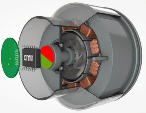
Fig. 4: A magnetic position sensor-on-chip is paired with a small, low-cost magnet.
A single-chip alternative to a discrete Hall sensor solution benefits from the following characteristics:
- Accurate absolute position information at all times, through 360°
- Simple assembly: The chip is mounted on a simple PCB and requires only one set of wire-to-board connections
- Low unit cost because an integrated circuit benefits from the economies of scale inherent in the semiconductor fabrication process
- Immune to contamination by chemicals, particles, or other materials
An example of such a single-chip Hall sensing product is the A5047 from ams, which has pioneered the magnetic position sensor product category. In the AS5047, ams has included features that make the sensor system easy to design in and manufacture:
- The acceptable range for the air gap between the magnet and the IC — typically 1 to 2mm, depending on the strength of the magnet’s field — allows for a large amount of tolerance in the production process.
- Likewise, permanent, absolute alignment of the rotor and stator is accomplished electronically after mechanical assembly through an on-chip OTP memory programming step.
- The differential sensing scheme implemented in ams position sensors provides for extremely high levels of stray field immunity, and so the special magnetic shielding arrangements necessary when using discrete Hall sensors are not required.
This simple solution can provide absolute position-sensing data from start-up to a high maximum speed of 28,000 rpm. Dynamic Angle Error Correction (DAEC) technology from ams internally compensates for propagation delay at high speeds, bringing the dynamic angle error down to no more than 0.36° at a constant speed of 28,000 rpm. A typical absolute position data update time of 222 ns means that absolute position information is available for use in real time across a wide range of rpm. Drawing on this position data, a motor control system can drive inconsistent loads without lag or lost commutation.
Paired with a low-cost circular, diametrically magnetized magnet, the AS5047 converts magnetic field strength measurements into position data. To ease system design, it can provide this data in the form of UVW output signals for steady-state commutation of motors with from one to seven pole pairs, as well as offering absolute 14-bit position data, incremental position data, and other position information formats if needed. This lightens the burden on the host processor and increases system efficiency.
By monitoring the absolute position at defined intervals, the system can instantly switch to absolute angle and computed drive under start-up conditions or for varying loads when only commutation management based on absolute stator/rotor position will offer optimal motor operation. This absolute position-sensing method can be implemented in all BLDC motor management schemes: six-step commutation, 12-step commutation, field-oriented control, and even PMSM-style sinusoidal drives.
The sensor also provides useful diagnostic information via its serial peripheral interface, when the magnetic field strength is outside its specified range and in the event of other operational faults, which enables the system to flag possible concerns that might require attention.
In conclusion, then, a sensor IC containing multiple on-chip Hall sensing elements is simpler to mount in motor assemblies than discrete Hall sensors, is cheaper than a resolver, avoids the optical encoder’s vulnerability to contamination and, unlike back-EMF sensing, provides accurate absolute position data at all times. By providing absolute position measurement, the AS5047 sensor enables a BLDC motor to be managed so as to provide smooth and predictable motor performance with optimal torque at all times. By using an integrated magnetic position sensor IC, then, manufacturers of power tools and similar end products can now replace brushed DC motors with the more modern, efficient BLDC motor type while maintaining the high motor performance that users expect.
Summary
Electric motor manufacturers have, in the past, met users’ requirements for smooth and predictable performance through the use of brushed DC motors, which maintain commutation and full torque at start-up and while managing varying loads. Counting against the brushed DC motor, however, are its relatively low efficiency and the inherent tendency for the brushes to fail before other components, due to mechanical wear or chemical contamination.
By contrast, brushless DC (BLDC) motors are greatly superior to brushed DC motors in many respects, including:
- Efficiency
- Zero electrical wear
- Clean operation
The main challenge for the designer of a BLDC motor control system is that the motor suffers from hiccupping and inconsistent torque and acceleration, when the commutator is forced to operate in the absence of accurate and real-time absolute rotary position data. Absolute position sensing has, in the past, only been available from extremely expensive sensors: The lower-cost sensing solutions suitable for the bill-of-materials budgets of most manufacturers have not met this requirement adequately.
In power tools and other performance-critical end products, then, efficient and reliable BLDC motor technology has generally not found favor. This article suggests, however, that power tool manufacturers and others with similar requirements could adopt the BLDC motor by taking advantage of a semiconductor product type — the magnetic position sensor IC — which, along with a simple magnet, provides absolute position data, comes at a low system cost, is easy to assemble into a motor system, and enables a BLDC motor to maintain optimal commutation at all times.
Advertisement


