BY CECILIA CONTENTI
Senior Marketing Manager
Infineon Technologies
www.infineon.com
Developing high-efficiency point-of-load (PoL) regulation schemes while reducing board space is a critical requirement for a wide range of server, storage, communication, and consumer applications. Furthermore, such PoL applications must be designed, tested, and implemented in ever-shorter design cycles. To address these challenges, engineers are increasingly looking for small-footprint integrated solutions that can help them simplify and speed their designs.
Requirements for PoL power
The PoL converter was a major step forward in power system architecture. Responding to the drive toward decreasing voltage levels and increasing current requirements, the PoL is a key facilitator in modern designs based on some form of distributed power architecture (DPA).
Use of a DPA approach of the type illustrated in Fig. 1 brings numerous benefits, including removing the single, central point of failure. However, where the PoL really proves its value is that higher bus voltages can be used right up to the point in the system where the conversion is needed, thus reducing distribution losses. Only at that point is the supply voltage converted to the low-voltage, high-current rail that the load (typically a processor) requires.
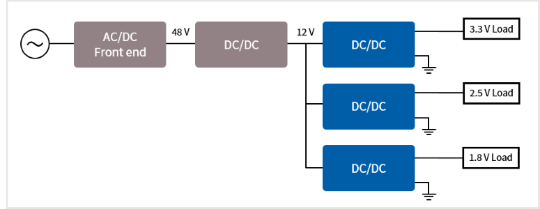
Fig. 1: Typical distributed power architecture.
“Headline” efficiency is generally measured at higher power levels — typically when the system is operating at 70% or greater of full output. However, in order to reduce energy usage, many systems now offer a “sleep” or “standby” mode, and this is the new focus for efficiency. Depending upon the operating-time to sleep-time ratio, the standby efficiency can be the critical driver defining the usage costs for the system.
Typical design challenges
Designing a power system is not a trivial task and is often seen as a specialist discipline to be outsourced rather than handled “in-house.” However, with well-documented off-the-shelf architectures, even non-specialist power designers can develop leading-edge solutions.
In most cases, the topology is the step-down converter (often referred to as a buck converter). Component selection is key, especially for the controller and power train components that will determine the system efficiency and performance.
As electronic systems become smaller or pack increased performance in the same space as the previous generation, space for the power scheme is often constrained. As a result, the pressure is on the designer to deliver ever-smaller power solutions with ever-increasing performance. Thus, a manufacturer is compelled to release products in increasingly compressed timescales and with as few “spins” as possible — preferably a single spin.
Noise (or mitigation against noise) remains a constant challenge for designers. Often unpredictable (especially with discrete designs), EMI/EMC is one of the most common reasons for initial designs to fail, leading to requirements for re-spin and retesting of the board — delaying the launch of (and revenue from) the new product.
Simplifying PoL system design
One of the easiest ways to simplify the process of PoL design is to use an off-the-shelf solution backed by strong application documentation. Following this approach allows the designer to take advantage of the extensive research and development investments made by manufacturers of PoL converters. The off-the-shelf solution also may allow access to additional features that would take time to develop from first principles while significantly reducing the risks of designing from scratch. The key is identifying and selecting a “standard” technology that provides enough features, performance, and flexibility to allow the engineer to configure the optimum solution for a given application at an economical total solution cost.
The best options typically provide a turn-key down-design approach for the designer with comprehensive reference designs, application notes and application diagrams, typical operating waveforms, suggested component lists, and even PCB metal and component placement diagrams. All of this reduces risk in the design, speeding development time and giving the designer confidence that the solution will be right the first time.
Down-designs of this kind offer an economical solution cost with high levels of optimization and integration that can significantly reduce the number of external components required. This also speeds time-to-market as well as reducing space demands and costs because there are fewer design decisions to be made and fewer components to find space for, procure, inventory, and place. Ultimately, this leads to an elegant technical and commercial solution.
Integrated silicon solutions
Integrated silicon solutions for power design stretch back around 40 years to the mid-1970s, when linear regulation was the normal approach. At this time, switched-mode design was in its infancy and understood by a select few — mostly in military spheres. As the first PWM controllers emerged, the technology became accessible to more designers and penetrated the commercial space, though the early controllers still required a significant amount of design input from the user. As time passed, more and more features were incorporated into controllers, bringing greater ease-of-use to designers and making more advanced features available to everyone. Continued innovation, driven primarily by the demanding needs of processors and “green-power” initiatives, has led to the incorporation of so-called “smart-power” features. Commonly, controllers have multiple modes of operation optimized for full-power and no-load operation. By detecting and responding to the changing load, the controller can ensure that the PoL is always operating at optimum efficiency.
The nature of the loads powered by PoL devices is also growing more complex. For example, dynamic power loads common in modern processors place new demands on the PoL. A popular technique to deal with this is constant-on-time (CoT), in which the control FET charges the output capacitor for a fixed time. CoT technology provides good load and line transient responses and generally does not require external compensation, leading to faster and easier design.
Many PoL devices now incorporate programmability of certain key parameters, such as the output voltage. From a system-level perspective, this provides simplicity because the same solution can be used for multiple voltages in a complex system with just component value changes. This leads to economies of scale as well as familiarity with that particular design. Also, as voltage rail requirements change, new values can be accommodated with minimal circuit changes and maximum confidence.
Together with efficiency, output voltage accuracy is a critical design parameter. This requires a very precise internal reference voltage over temperature. And standard features like enable and power good output are a must-have for every PoL design.
Stability of the system, including the PoL, is critical. As today’s loads become more dynamic and complex in nature, a good design must take this stability into account. One of the limitations of state-of-the-art CoT solutions is poor stability when using ceramic capacitors. More and more modern systems use only ceramic capacitors to meet cost, size, and reliability objectives. This capacitor type has low equivalent series resistance (ESR), and the ripple signal is generally too small to allow the standard CoT topology to work correctly without external compensation. This generally calls for external ripple injection (R+C) and snubber components for stability with all ceramic capacitors. An alternative is to add an internal ripple emulation circuit to overcome this limitation, providing stability with ceramic capacitors without the need of external compensation or extra components.
Protection requirements
One of the best measures of any system is its reliability — especially in the area of up-time for mission-critical applications (such as servers, communications, and storage). The power system is a fundamental component of this reliability, and to achieve this, many protection features are now incorporated into modern controllers.
The power system itself should not fail, but it needs to protect the rest of the system as well as itself from failures that might occur elsewhere. To accomplish this easily, choosing controllers that incorporate features such as over-current protection, thermal shutdown, and pre-bias start-up can be important. In particular, precise thermally compensated current limit with multiple settings is critical to minimize inductor size and cost.
Silicon evolution
An example of how silicon integration supports this evolving set of feature demands is the IR MOSFET IPOL (IR3883) high-efficiency DC/DC converter, shown in Fig. 2 .
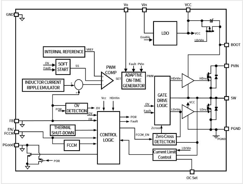
Fig. 2: The IR3883 controller IC is supplied in a compact, 3 x 3-mm QFN package.
This compact, highly integrated device offers ultra-light-load efficiency (including standby power), CoT operation, and programmability. It can operate with a wide input voltage range (2.5 to 14 V), making it suitable for most PoL low-current applications. It includes all features and fault protections required for a reliable PoL design (enable input, power good output, soft start, pre-bias start-up, thermal shutdown) and a very precise reference voltage (0.5 V ±0.6%) for very high output voltage accuracy.
This versatile PWM controller with integrated MOSFETs has a small, 3 x 3-mm footprint capable of delivering up to 3 A constantly. It requires an absolute minimum of external components (see Fig. 3 ) and consumes less than 10 μA at shutdown and less than 200 μA operating with no load, making it ideal for standby operation.
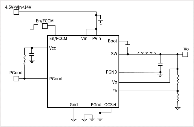
Fig. 3: IR3883 application diagram showing reduced components count.
Efficiency is optimized through two operating modes. In forced continuous conduction mode (FCCM), the controller operates as a synchronous buck converter with a pseudo constant switching frequency of 800 kHz. In diode emulation mode (DEM), the synchronous FET is turned off as inductor current drops to zero, thus improving light-load efficiency. As shown in Fig. 4 , ultra-low quiescent current ensures efficiency for load currents as low as 10 mA, which is ideal for standby rails.
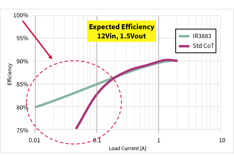
Fig. 4: In DEM, the IR3883 offers excellent low-power efficiency — making it highly suitable for standby rails.
Thermally compensated internal overcurrent protection with different settings avoids the need to over-design the inductor saturation point, allowing the selection of a smaller and cheaper inductor. The option to force continuous current mode allows applications in which frequency reduction could be a problem for harmonics, beat frequency, and interference, like multi-rail systems and communication applications.
A proprietary CoT engine is stable with ceramic capacitors. No external compensation is needed, which enables small and low-cost MLCC capacitors to be specified. An ability to tolerate wide variations in capacitance delivers increased robustness, while proprietary internal ramp compensation further reduces ripple and allows voltage feedforward to preserve loop response across a wide input voltage range. This ensures stability over a wide range of operating conditions and removes the need for complex AC analysis or Bode plots.
The pin assignment and footprint of IR3883 also is optimized based on component placement for easy layout and low noise (see Fig. 5 ). For example, the Power Ground and Power Input Voltage pins are adjacent to each other to allow perfect placement of the input capacitors for maximum input filtering. This simplifies the layout for a “fully comprehensive” easy approach.
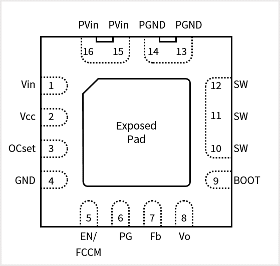
Fig. 5: IR3883 showing footprint and pins placement optimized for easy layout and input cap by passing.
Distributed power architecture naturally lends itself to large systems and is very widely used in server, storage, communication, and consumer applications — all areas where the overall system efficiency is crucial and often a competitive advantage for the manufacturer. Additionally, DPA/PoL architectures are increasingly being used in industrial equipment and telecom systems in which the advantages of enhanced resilience and efficiency are also valued. In all of these areas, availability of high-integration controllers simplifies design and speeds time-to-market while achieving targets for efficiency at any load level.
Advertisement
Learn more about Infineon Technologies


