BY DIRK SEIDEL
Senior Marketing Manager, Industrial, Lattice Semiconductor
www.latticesemi.com
Today’s electric motor drive market offers system designers more options than ever before. On the AC side, motor drives provide highly flexible solutions with a growing array of features like variable speed control. These devices can feature low power demand on startup, controlled acceleration, adjustable operational speed, controlled starting current, adjustable torque limit, and reduced power line disturbances.
AC motors come in two general types. The first is AC motors, which synchronize the rotation of the rotor with the frequency of the supply current. This allows speed to remain constant under varying loads, making these motors ideal for driving equipment. Designers typically use synchronous AC motors in applications requiring high-precision positioning such as robots, instrumentation, machines, and process control.
The more common AC motor in use today is the induction or asynchronous type. These motors use electromagnetic induction from the magnetic field of the stator winding to produce an electric current in the rotor and, hence, torque. This load capacity can be employed in a wide range of applications.
These devices come in both single-phase and three-phase versions. The single-phase AC induction motors are widely used for smaller loads like household appliances. The three-phase induction motors are found in higher-capacity industrial applications such as compressors, pumps, conveyor systems, and lifting gears.
DC motors for industrial use
In the industrial arena, designers typically use brushed DC, brushless DC (BLDC), stepper, or servo motors. Each type of motor brings its own tradeoffs.
Brushed DC motors offer a simple, lower-cost option. The speed that they support is linear to the applied voltage so that they can be used with simple motor-control solutions. On the other hand, brushed DC motors typically require relatively high levels of maintenance and offer a relatively short lifespan due to physical wear and tear that they must endure.
The BLDC motors are also a highly efficient option. By replacing the conventional mechanics in a brushed DC motor with electronic commutation, they deliver 20% to 30% improved efficiency running at the same speed and load as conventional DC motors. This allows designers to use smaller, lighter, and quieter BLDC motors for a given power output. Unfortunately, in many applications, these motors require more complex and, oftentimes, more expensive motor-control solutions.
Servo motors employ closed-loop mechanisms that use position feedback to control the motor’s motion and position. The motor is typically paired with some type of encoder to provide position and speed feedback. Constant feedback eliminates the potential for stalling and allows the motor to correct any positioning discrepancies.
Stepper motors are brushless DC motors that move in discrete and equal steps. The motor can be directed to move or hold its position at any step without any position sensor for feedback. Stepper motors use more poles than servo motors. For designers seeking motors with highly accurate control and robust low-speed torque, stepper motors offer the best option. Stepper motors also offer a long lifecycle.
But the high accuracy comes at a cost. Steppers are relatively low-efficiency motors and are prone to resonance, noise, and torque ripple. Designers using this motor type must also remember that they cannot accelerate loads rapidly. In many cases, stepper and servo motor drives offer designers significant advantages when used with FPGAs in motor-control applications.
FPGA-aided motor control
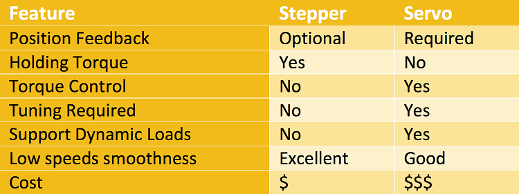
Stepper and servo control drives are tailored to specific needs. Servo control drives are ideal for high-speed, high-torque applications that involve dynamic load changes. Stepper control systems, on the other hand, are considerably less expensive and best-suited for applications that require low-to-medium acceleration, high-holding torque, and the flexibility to operate in either an open or closed loop. Table 1 compares the feature available with both stepper and servo control drives.
Table 1: Stepper and servo motors feature comparison.
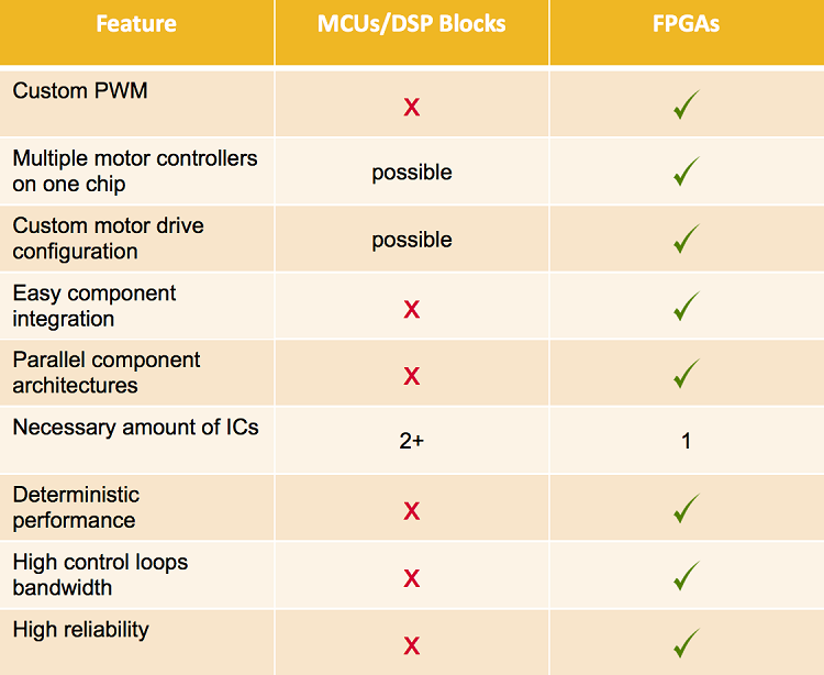
Typically, FPGA-based motor control drives are used to replace MCU and DSP alternatives. Table 2 compares motor control drive designs based on MCU/DSP blocks with FPGAs and highlights the advantages that FPGAs offer, including the ability to use custom pulse-width modulation (PWM), easier component integration, fewer components, higher control-loop bandwidth, and higher reliability.
By using FPGAs with custom IP, system designers can efficiently create motor-control solutions according to their needs and ensure deterministic behavior. They can also develop solutions that reduce losses in the motor and the power converter while optimizing the voltage utilization of the DC bus. Moreover, designers taking this approach can customize what previously was fixed generic hardware while reducing total harmonic distortion (THD) by nearly 50% at a high modulation index.
Table 2: Comparison of MCU/DSP- and FPGA-based motor-control solutions.
How does a designer know if an application can benefit from an FPGA-based control solution? Answering a few basic questions is the first step. What design criteria is the designer using? What is the load that the application must move? At what speed does the motor need to run? Does the load vary throughout the move? Does the application require any special functions such as torque limiting? And, finally, how large is the design and power budget?
The block diagram (Fig. 1 ) illustrates how engineers at DVE developed a motor-control solution for a stage-lighting application that had to synchronize up to eight stage lights simultaneously in a single module. The design team knew that they needed a low-cost motor-control solution that could drive up to eight two- or three-phase stepper motors simultaneously.
The design called for a 32-bit processor or DSP operating at 100 MHz with additional logic. Next, it mandated careful software design due to the required simultaneous and deterministic system requirement. The design also needed support for an encoder interface for each motor to allow precise position determination.
Design case study
To address these needs, the designers used a MachXO2-7000 FPGA from Lattice Semiconductor. Featuring up to 256 Kbits of integrated Flash memory and 240 Kbits of embedded RAM, this ensured that the FPGA could boot on its own in less than a millisecond. All in a single chip, the design included a 32-bit microcontroller running at 50 MHz with 20 Kbytes of code and 4 Kbytes of data space, a real-time Ethernet interface, a motor-control algorithm, and feedback encoder.
In addition, the integrated boot Flash eliminated the need for an external boot Flash and ensured fast boot process. Due to the parallel architecture of the FPGA, functional blocks could simply be replicated without sacrificing deterministic behavior.
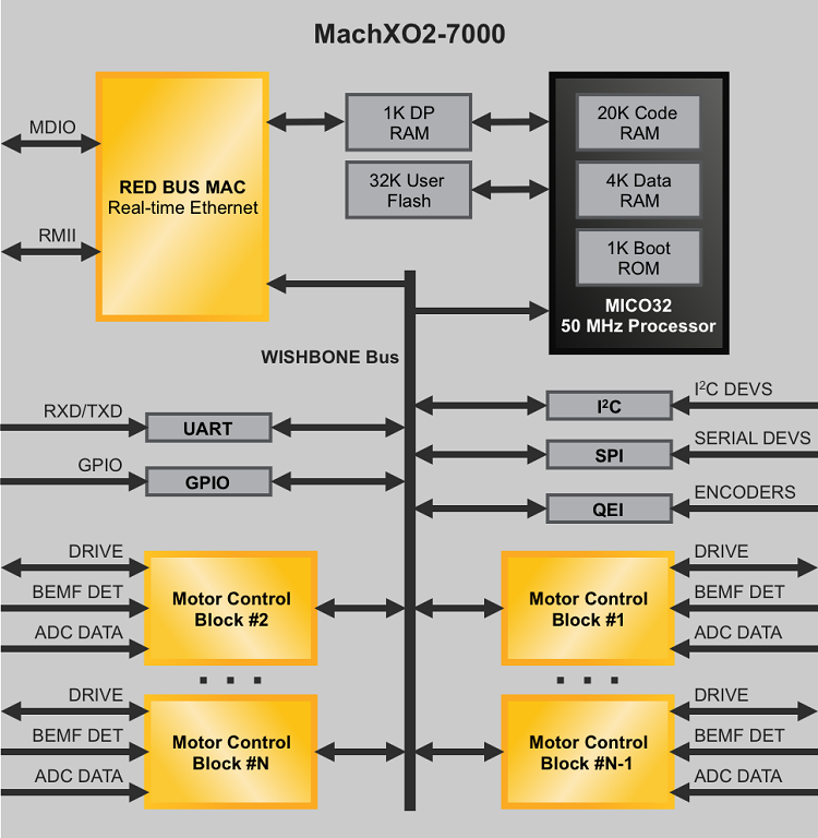
Fig. 1: Motor-control solution designed by DVE with a single-chip FPGA.
DVE’s motor control solution supports space vector modulation algorithms for the control of pulse-width modulation and back-EMF detection techniques. It also features a REDBUS real-time Ethernet interface that allows 100-Mbps data exchange and the interconnection of multiple boards without Ethernet switch devices.
Looking forward, servo motor control applications typically require a feedback loop where a sensor can determine the position of the motor, at what speed it is operating, and how much torque it is applying. For these applications, designers will need an FPGA with integrated DSP blocks to perform the feedback loop functions. A new generation of low-density FPGAs featuring embedded DSP blocks can offer a more efficient solution than traditional options.
Advertisement
Learn more about Lattice Semiconductor


