BY DR. MICHAEL HALLWORTH
Senior Design Engineer, XP Power
www.xppower.com
Digital power has experienced rapid growth over the last five years with industry taking advantage of the benefits that digital control brings to a traditionally analog domain. This has been supported by the many new products from various microcontroller vendors that specifically target the digital power market.

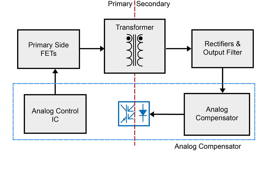
Fig. 1: An analog controlled power supply.
In a traditional analog power supply, the control is implemented using a control IC consisting of operational amplifiers and comparators combined with a series of carefully selected external capacitors and resistors forming the compensation network. These give the power supply the desired transient load performance and stability in the frequency domain, the s-domain. The compensation network is fixed and often compromised by the presence of the bandwidth-limiting optocoupler in the feedback path. This is shown in Fig. 1 .

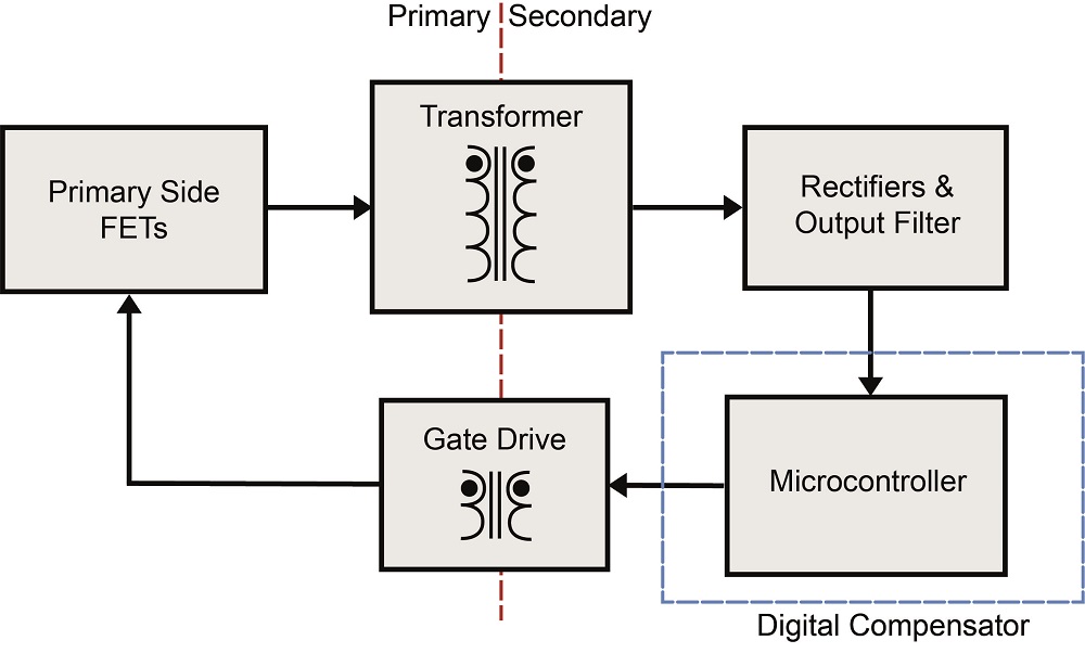
Fig. 2: A digital controlled power supply.
When we refer to digital power, what we mean is a digital control loop, which regulates and stabilizes the power supply. This replaces the analog control ICs that have been used in switch-mode power supplies since the 1980s. In the digital power supply shown in Fig. 2 , the analog control IC and its associated analog compensation network has been replaced by a microcontroller.
The microcontroller is used to close the feedback loop of the power supply. In a typical digitally controlled power supply, the analog-to-digital converter (ADC) module on-board the microcontroller samples the output voltage or current. This is compared to a demand reference value with the result being an error term. The error term is then used as an input to the discrete-time controller (usually a two-pole, two-zero or a three-pole, three-zero controller), which has poles and zeros in the discrete-time domain, the z-domain. The discrete-time controller is executed at exact and pre-defined intervals — each time, there is a new ADC sample available.

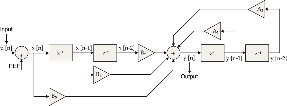
Fig. 3: A discrete-time two-pole, two-zero controller.
An example of this discrete-time controller is shown in Fig. 3 . The controller consists of five multiply-and-accumulate operations, which are referred to as multiplier-accumulator (MAC) instructions on-board a digital signal processor (DSP). The input to the controller for this sampling period x[n], the error term, is multiplied by the controller coefficient B0. The z-1 term is a unit delay and results in the previous input to the controller, x[n-1], being multiplied by the coefficient B1. Following this, there is another unit delay, so the error term from the two previous sampling periods, x[n-2], is multiplied by B2.
On the right-hand side of Fig. 3 , the same process is applied to the outputs of the controller. The previous output of the controller, y[n-1], is multiplied by A1 and the output from the two previous sampling periods, y[n-2], is multiplied by A2. These multiplications are accumulated together and the result is the new output of the controller for this sampling period. The output of the controller, y[n], is the new value of duty cycle for pulse-width-modulated (PWM) converters or switching frequency for resonant/pulse-frequency modulation (PFM) topologies.
Just like the analog compensators in the s-domain, the discrete-time controller shown in Fig. 3 will have a frequency response in the z-domain. It is the controller coefficients that determine the frequency response and, hence, the stability of the power supply. Therefore, the engineer must analytically calculate the controller coefficients to stabilize the power supply.
Microcontrollers have been used in power supplies for many years for the purposes of implementing basic functionality such as PMBus and fan-speed control using relatively simple and low-cost microcontrollers. However, full digital control has previously been most prevalent in the server and telecom market with uptake in the industrial and medical markets lagging.
The prohibiting factors to the switch to digital control have been predominantly the cost and complexity associated with digital power. The good news is that the cost of a modern microcontroller with the DSP functionality needed to implement full digital control has decreased dramatically in recent years, making their use viable for many more designs. However, the complexity remains an issue. This complexity stems from the need for a mixed-domain approach to designing the power supply. Engineers need to combine their power supply design knowledge with the ability to write efficient code and stabilize the discrete-time control loop.
So what are the reasons for switching to digital control? The digital control loop has many advantages over its analog counterpart. The digital power supply is insensitive to the environment, temperature, aging, and tolerances of the control loop components. It allows the system to monitor the performance of the power supply in real time and adjust parameters to tune the performance as required.
Furthermore, advanced discrete-time control techniques allow us to achieve higher performance compared to analog compensators, recovering from transients in a matter of a few switching periods. This has been of particular interest for the point-of-load (POL) converter market, which has been a big adopter of digital power. One high-performance microcontroller can be used to stabilize and regulate multiple power stages — negating the need for individual analog control ICs for each power stage.
The ever-increasing demand for high-efficiency converters is an area in which the flexibility of digital power offers solutions beyond the capability of typical analog control schemes. This can involve adjusting the operation of the PSU to achieve optimal zero-voltage or zero-current switching, reducing switching losses and increasing the overall efficiency.
Alternatively, we can also consider the impact of improving the efficiency of the overall data center or system in which multiple power supplies are used. This could be achieved by responding to requests to shut down or enter low-power mode based on information from a master controller within the system.

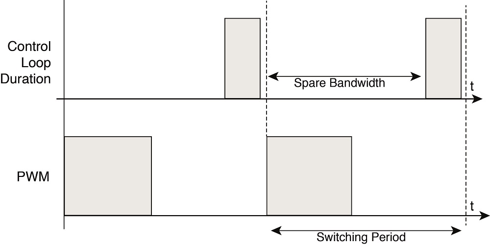
Fig. 4: Typical control loop duration vs. PWM switching period.
The latest microcontrollers for digital power applications contain DSP functionality, allowing the digital control loop to execute within a fraction of a single PWM switching period every switching period. Fig. 4 shows the PWM switching period of a typical digital power supply. In this simple example, the output voltage is sampled once per switching cycle. An ADC conversion time of a few hundred nanoseconds is typical for a microcontroller designed for digital power applications.
Following the ADC conversion, the interrupt service routine is called to execute the discrete-time controller. This is a time-critical routine, and therefore, the controller can be written in assembly code to make use of the MAC instructions and optimize the use of every single instruction cycle.
As shown in Fig. 4 , for this example, the time that the MCU does not spend executing the controller is our spare bandwidth. This spare bandwidth can be used to perform other tasks or functions specific to a customer application. Any low-priority tasks are run in a slow loop and will be interrupted whenever the high-priority tasks occur such as the ADC interrupt to run the control loop code.
The development of robust and efficient firmware for a power supply can take a significant amount of time depending on the complexity of the design. Added to this is the verification and testing process and the documentation required for various safety approvals. Therefore, substantial resources need to be invested into the development of a digital power supply. However, once the initial investment has been made, the firmware can be reused across many different products. For example, the change in firmware for products with different output voltages within one series may be a simple case of changing the controller coefficients.
Given the flexibility that a microcontroller adds to the design, digital power lends itself well to custom power applications in which standard products may not satisfy all of the customer's requirements. There may be specific communication requirements such as controlling the power supply over USB, I2 C, or EtherCAT combined with the possibility of updating the communication protocol at a later date using a live firmware update. The customer may require the output voltage or current limits to be adjusted on the fly or require real-time monitoring, power rail sequencing, or accurate current share between output modules.
Certainly, the high-performance microcontroller used for digital power will be costlier than the analog IC that it replaces. However, the digital controller opens up the opportunity to implement other functionality within the MCU rather than using discrete components. This can lead to a reduced component count and more compact solutions, especially for designs with complex signal requirements or multiple power rails, which could be controlled using one microcontroller. The result may be an overall solution that is more cost-effective when implemented using a microcontroller over an analog solution. Of course, for some complex requirements, going digital may be the only solution.
XP Power has the capability to implement complex custom power solutions utilizing the diversity of our standard product range. With an MCU at the heart of the power supply, the possibilities for custom power applications are far-reaching. Given the many benefits that digital power offers, we are likely to see an ever-increasing presence of digital power over the coming years.
Advertisement
Learn more about XP Power


