BY MICHAEL O’LOUGHLIN
Systems Application and Design Engineer, High-Voltage PWM Controller Product Group, Texas Instruments
www.ti.com
The quasi-resonant flyback (QRF) power converter is a popular choice in low-power offline applications in the 150-W-or-less output power range for many reasons. The QRF converter has a low component count, which translates into a low-cost bill of materials. The topology can hit system efficiencies as high as 90% to 91% when synchronous rectifiers are used on the converter’s output.
To manage heat and power dissipation in the traditional QRF, engineers have limited the maximum switching frequency (fsw ) of their designs below 100 kHz. The only problem with this is that consumers would like their adapters even smaller than they are today. To accomplish this, it requires being able to run the offline flyback converter at switching frequencies at least two to three times greater than the QRF is presently used to reduce magnetic size. In this article, we discuss how using an active clamp flyback (ACF) converter for these applications can run faster and cooler than a traditional QRF, enabling the reduction of magnetic size in offline flyback applications and making the overall power supply smaller.
QRF switching losses increase with frequency
The QRF converter is a very efficient power converter because of its ability to valley switch, which has lower switching losses compared to traditional hard-switched flyback converters. However, the QRF does have switching losses (Q1 ) that increase with switching frequency, especially at high input voltages.
Equation 1 expresses the QRF switch-node (VSW ) switching losses (PSW(QRF) ), where NP /NS is the flyback converter’s transformer turns ratio (T1 , Fig 1 ). Variable CSW is the flyback converter’s switch-node (VSW ) capacitance. From this equation, it can be observed that PSW(QRF) will increase fSW .


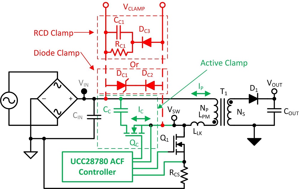
Fig. 1: Offline flyback converter showing an RCD, diode, and active clamp.
Passive clamp losses increase with switching frequency
Another problem with the traditional QRF converter is that it traditionally uses a diode clamp or resistor capacitor diode (RCD) clamp to provide a current path to de-energize the transformer’s (T1 ) primary leakage inductance (LLK ) and protect the converter’s main switch (Q1 ) from electrical overstress and damage. Unfortunately, these passive clamps are not free, and they dissipate power (PCLAMP ) that increases with switching frequency (fSW ).
See how Equation 2 calculates the flyback passive clamp power dissipation (PCLAMP ). In this equation, VCLAMP is the voltage across the clamp when Q1 is off, and IP is the transformer’s peak primary current. Similar to the switch-node losses, the clamp losses also increase with fSW .

The PCLAMP and PSW(QRF) losses in QRF with a passive clamp are detrimental to high-frequency designs. If you try to reduce the power converter’s magnetic size by running the design at a higher switching frequency, you will have to increase your heat sink size for Q1 , hurting the design’s power density. The increased losses will hurt system efficiency and require the use of higher power-rated and more expensive components for the main switch and passive clamp. This discourages most designers from designing QRF converters over 100 kHz.
ACF recycles clamp energy
The active clamp in Fig. 1 consists of a clamp switch (QC ) and a clamp capacitor (CC ) that replaces an RCD or diode clamp. This gives a place for the discharge and storage of transformer T1 ’s leakage inductance (LLK ) and thus protects Q1 from electrical overstress. Because QC allows bidirectional clamp current (IC ), the leakage energy can be returned to the output through the flyback converter’s transformer primary-to-secondary turns ratio (NP /NS ) every switching cycle, making the active clamp near lossless and a better choice for higher-frequency designs in the 200-kHz range or higher.
ACF can achieve zero-voltage switching
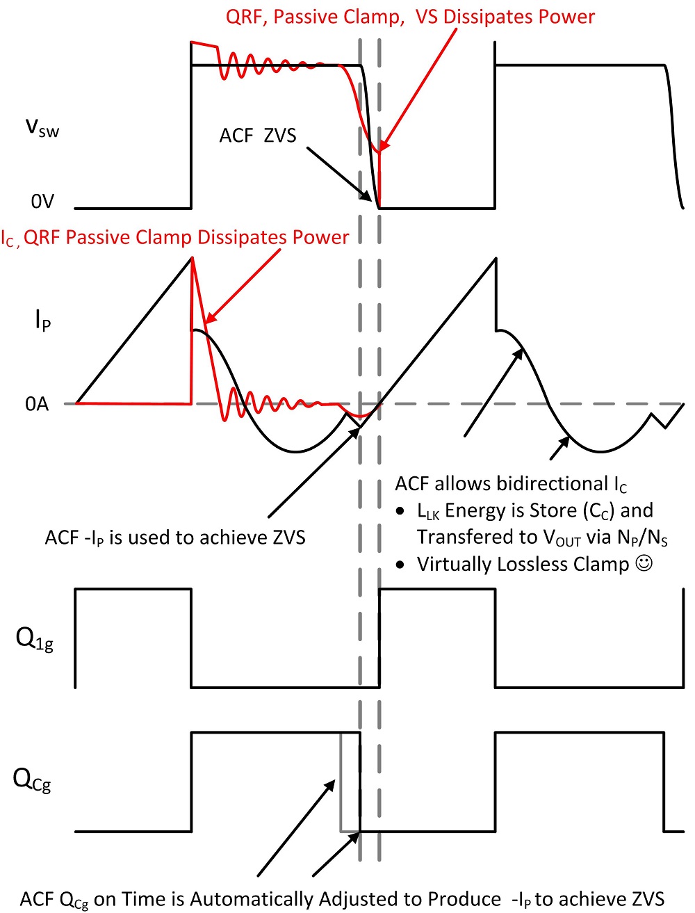
There are pulse-width modulator (PWM) controllers on the market that are designed for use in active clamp power converters that have two drive outputs for QC and Q1 . The power supply designer can then take advantage of bidirectional current by delaying the turn-off of the clamp switch. This delay allows the primary magnetizing inductance (LPM ) to charge in the reverse direction and develop a negative peak primary current (–IP ) large enough to resonate with the switch-node capacitance (CSW ) to achieve zero-voltage switching (ZVS).
The delay does require adjusting the turn-off delay of switch Q1 , allowing the power converter time to achieve ZVS. It will require some work in the lab, but removing the switching losses is well worth the effort.
To achieve ZVS, the energy in LPM needs to equal the energy in CSW . This relationship is shown in Equation 3:

Calculating the amount of negative current that is needed to achieve ZVS can be derived by algebraically solving for I P from Equation 3, which yields Equation 4:

To make the design process easier, Texas Instruments developed the UCC28780 active flyback controller. The UCC28780 monitors the switch node and will adjust the Q C turn-off delay and Q 1 turn-on delay to achieve ZVS. The controller continuously monitors the switch node and will adjust the delays within a few switching cycles to ensure that the design still achieves ZVS if the line voltage and/or the power converter load should change. This should reduce the active clamp flyback converter’s design cycle time, reducing development costs even further.
Fig. 2 shows a graphical comparison between QRF and ACF switch-node switching and transformer primary current. There are notes in this waveform describing why ACF is more efficient than the traditional QRF flyback.

Fig. 2: ACF ZVS and active clamp vs. QRF and passive clamp.
Summary
When designed correctly, the ACF controller will not only recycle transformer leakage energy to remove switch-node clamping losses but can also achieve ZVS, removing primary switching losses. This enables designers to push the flyback power converter’s switching frequencies from 100 kHz to 200 kHz or more without adding additional heat sinking, which then allows them to reduce the design’s magnetic size and increase power density when compared to a QRF using passive clamps.
Advertisement
Learn more about Texas Instruments


