By Maurizio Di Paolo Emilio, contributing writer
The amount of noise in a motor depends on the type of motor, environmental conditions, and the specific application. Permanent magnet and hybrid stepper motors are generally quieter, as they have a more consistent rotation. Conversely, variable reluctance stepper motors are the noisiest, regardless of the application in which they are used.
To better understand the origins of noise, we need to think about how the rotation movement takes place. When a stepper motor performs a step, it does not stop immediately but continues to move slightly forward and backward before stopping completely. This type of behavior can be overcome by adopting a particular control logic in the motor driver. During motor operation, the driver commands the movement of the next step one moment before the motor has stopped after completing the previous step. This continuous and regular motor advancement helps to reduce both noise and vibration.
It should also be noted that each stepper motor has a resonance frequency, which typically occurs when the motor moves at speeds between 150 and 300 steps per second. Many designers tend to avoid this operating speed range in order to minimize both noise and vibration. The insertion of gearheads, appropriately designed and sized, can help to reduce vibration. Rear-mounting dampers positioned on the crankshaft are another traditional solution for reducing vibration.
Noise-reduction techniques
Most stepper motors are controlled by a pulse-width modulation (PWM) signal, which continuously forces the switching of the H bridge between the on and off states, thus regulating the current that feeds the motor. Driver circuits based on this technique are commonly called “chopper drivers” because they supply the motor windings with a constant current by chopping the output voltage following the application of the PWM waveform.
Unlike the L/R technique, which instead aims to keep the voltage applied to the windings constant, current chopping has the advantage of being a very efficient, compact, and economical solution, generating a small amount of heat.
However, the PWM signal has a side effect: The modulated signal applied to the stepper motor can generate an audible signal, even more so if the PWM frequency falls within the audio band. Experimentally, it is indeed easy to verify how a stepper motor can generate noise even when it is stopped or when it holds the position. This phenomenon occurs mainly at switching frequencies below 20 kHz.
Thus, it can be deduced that the first method to reduce noise is to increase the switching frequency. Most chopper drivers offer the capability to increase the switching frequency by modifying the value of an external resistor or capacitor. The effect is to change the duration in the off state of the PWM signal used for current regulation. The shorter this duration, the higher the switching frequency.
However, it is not necessary to exceed the frequency value because, beyond a certain limit, the switching losses also increase. An appropriate switching frequency value could be between 30 and 50 kHz. If this technique is not sufficient, the current applied to the motor windings can be reduced. Lower current means, in fact, a reduction of vibration and, therefore, of noise.
However, a side effect is a reduction in torque, which, if too low, can cause the loss of steps during operation. Because the motor is controlled in an open loop, the motor must be supplied with the amount of current sufficient to cover all operating conditions, even the most severe. A good compromise is to reduce the current during periods when the motor is stopped.
Normally, the current required by the motor to maintain the position is considerably lower than the current required to accelerate or move the motor at a constant speed. Virtually all stepper motor drivers allow setting the current value by modifying the analog reference voltage VREF . The trip current, ITrip , is a function of both the external RSENSE resistor and the VREF reference voltage. Because the first, once chosen by the designer, has a fixed value, at run time, it is possible to modify ITrip by changing VREF on the fly.
If further noise reduction is required, the motor may be operated in slow-decay mode instead of fast- or mixed-decay modes. This mode minimizes the driving current ripple, reducing the noise and increasing the driver efficiency. Slow-decay mode, however, is not always the best solution, especially if you want to use the micro-stepping technique.
Stepper drivers
Integrated drivers have been designed to offer easy configuration and advanced control functions for every type of application. Integrated encoder options make stepper motors a suitable choice for synchronized position applications. The stepper motors are driven by connecting the coils to power transistors and the transistors to a control circuit.
Allegro MicroSystems, a leader in the design and manufacturing of brushed DC and stepper motor drivers, provides a broad portfolio of safe and robust solutions with integrated and MOSFET gate drives. Suitable for low- and high-power applications, Allegro’s A3982 is a complete stepper motor driver with a built-in translator for easy operation. Designed to operate bipolar stepper motors in full- and half-step modes, the driver can provide an output signal up to 35 V and ±2 A. The current decay mode (slow or mixed) can be selected by applying a signal at the STEP input pin, as shown in the schematic block diagram of Fig. 1 .
In mixed mode, chopping control is initially set to a fast decay for a period amounting to 31.25% of the fixed off time, then to a slow decay for the remainder of the off time. This current decay control scheme results in reduced audible motor noise, increased step accuracy, and reduced power dissipation.
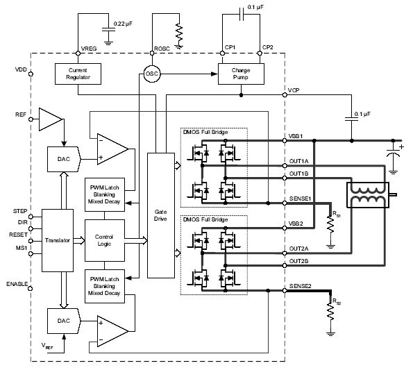
Fig. 1: A3982 block diagram (Image: Allegro MicroSystems)
The translator feature greatly simplifies the design of the motor control system. By applying one pulse on the STEP input pin, the motor is driven one step. No phase sequence tables or high-frequency control lines are needed, making the A3982 the right choice for applications in which a host microcontroller is unavailable or is overburdened.
Toshiba Electronic Devices and Storage Corp. also offers a wide selection of stepper motor drivers. The TB67S128/249/279/289 devices feature the proprietary Active Gain Control (AGC) technology. AGC dynamically adjusts the stepper motor driving current in order to address heavy torque conditions, resuming normal current value in real time and in open-loop designs. AGC technology saves significant power and reduces or eliminates a more complex closed-loop design.
The TB67S128/249/279/289FTG devices provide 5.0 A, 4.5 A, 2.0 A, and 3.0 A, respectively, with 10-V to 42-V motor operating voltage. These devices also include a 32-step and 128-step micro-stepping capability in one quadrant that makes them suitable for a wide range of industrial precision motor control applications (Fig. 2 ).
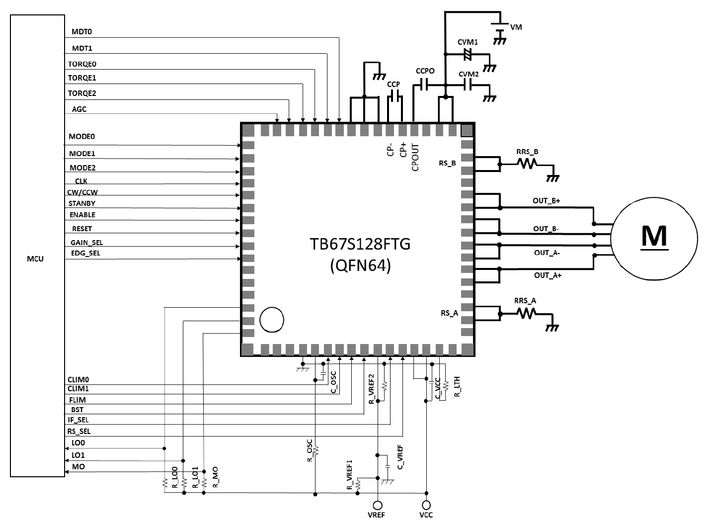
Fig. 2: Typical application of the TB67S128 motor driver (Image: Toshiba)
Conclusion
Stepper motors have a simple structure and are easy to control. As a digital electronic component, stepper motors are widely used in many open-loop control systems. However, it has a disadvantage in relation to the noise that affects the overall performance. The noise and the resonances come mainly from the drive circuit and from the mechanical structure of the resonance. Most stepper motor applications require smooth movement. To obtain extremely fluid movements, some engineers modify the voltage, current, and, more often, the micro-step setting.
Related article:
Motor control design: An introduction to motors and controllers
Advertisement
Learn more about Electronic Products Magazine


