Solutions for asynchronous serial communication between systems or subsystems include many possible interface implementations – for example, RS-232, RS-485, RS-422, controller area network (CAN), Ethernet, Local Interconnect Network, Highway Addressable Remote Transducer, IO-Link, and wireless protocols like Zigbee or LoRa. In many cases interoperability concerns are the biggest deciding factor when selecting a protocol, especially if you’re designing a subsystem that must communicate with existing networks and installations, or be backwards-compatible with a previous-generation design.
But for newer applications without these restrictions, choosing the right interface implementation involves evaluating a series of trade-offs between factors such as communication bandwidth, distance, bus topologies and node counts, bus access methodologies, solution cost, and the ability to interoperate with other systems.
This article aims to help you make a more informed interface selection through a high-level overview of a few common standards: RS-232, RS-422 and RS-485, and CAN. These standards continue to see wide adoption in industrial communications because of their robustness, ease of implementation and ability to serve common application requirements, and their usage is expected to persist for some time – despite the introduction of newer communication technologies.
RS-232
RS-232, originally standardized in 1960 by the Electronic Industries Association (EIA), is one of the oldest digital communication technologies still in active use. The current version of the standard is Telecommunications Industry Association (TIA)-232-F and describes a single-ended signaling scheme that is point to point in nature (as shown in Fig. 1) and intended to operate between data terminal equipment (DTE) such as PCs and data circuit-terminating equipment (DCE) such as modems.

Fig. 1: Point-to-point connection (Image: Texas Instruments)
TIA-232-F defines several different physical signals:
- Data carrier detect (DCD) from DCE to DTE.
- Data set ready (DSR) from DCE to DTE.
- Receive data (RD) from DCE to DTE.
- Request to send (RTS) from DTE to DCE.
- Transmit data (TD) from DTE to DCE.
- Clear to send (CTS) from DCE to DTE.
- Data terminal ready (DTR) from DTE to DCE.
- Ring indicator (RI) from DCE to DTE.
The TD and RD (sometimes referred to as TxD and RxD) are used to transmit serial data, while the other signals help manage the flow of data between systems. This flow control is present in order to ensure that systems receive serial data only when they are able to process it, so that buffer overruns do not occur when there is a mismatch in operating speeds between devices. In many modern implementations, though, physical flow control signals are often reduced in number or omitted entirely in favor of software-based flow control.
Logic-low or logic-high states are represented on the line as either positive or negative voltages, respectively, whose amplitudes at the transmitter output could vary from ±5 V to ±15 V with respect to ground (assuming standard receiver loading conditions). In many modern implementations, transceivers with integrated charge-pump circuits generate these higher voltage bipolar rails based on lower voltage logic supplies such as 5 V, 3.3 V, or 1.8 V. Receiver circuits can reliably detect high and low states as long as they exceed ±3 V in magnitude. Example transmit and receive waveforms are shown in Fig. 2.

Fig. 2: RS-232 transmit and receive waveforms (Image: Texas Instruments)
These relatively high voltages help extend the interface over reasonable cable connections and provide some level of noise immunity. However, the larger signal swing does result in relatively slow communication (low baud rates), since the transition or slew rate of the transmitter output must be limited for electromagnetic interference (EMI) reasons. Because of this limitation, the TIA-232 standard specifies a maximum baud rate of just 20 kbits/s. Many modern implementations deviate from the standard in this regard, however, and transceivers capable of higher speeds (1 Mbits/s) are available.
The cable lengths achievable are limited compared to newer interface standards employing balanced differential signals. Interconnect capacitances are limited to 2500 pF, which often translates to a cable length around 15 to 20 meters (m).
Another disadvantage of the standard for many applications is its inability to support multipoint buses; only point-to-point connections are allowed, and the number of interconnected nodes is thus limited to two.
Despite these disadvantages, RS-232 is still popular given its ease of implementation, ubiquity across end equipment, and decades of installation in the field.
RS-422 and RS-485
RS-422 (TIA/EIA-422) and RS-485 (TIA/EIA-485) support higher speed communications across longer distances by making use of balanced differential signaling rather than single-ended (ground-referenced) signaling. In other words, logic-high or logic-low states are represented by positive or negative voltage differences between the complementary noninverting and inverting halves of a signal pair. These halves are typically referred to as Y and Z for transmitters and A and B for receivers. (Half-duplex implementations using a single pair for data in both directions typically only use A and B naming.) Example transmit at receive waveforms are shown in Fig. 3.
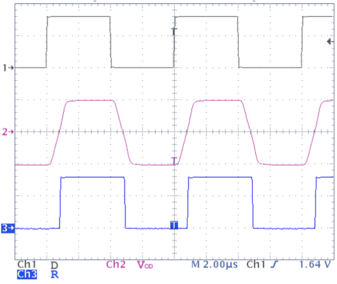
Fig. 3: RS-485 example waveforms; channel 2 (VOD) shows the voltage at A with respect to B (Image: Texas Instruments)
The use of differential signaling provides several advantages:
- Using two complementary signal lines effectively doubles the signal amplitude transmitted, enabling longer-distance communication using transceivers powered with standard low-voltage rails (such as 5 V or 3.3 V).
- Because the receivers sense a difference between two signal lines, the communication is more immune to slight differences in local ground potentials (which would create voltage offsets on a ground-referenced signal) and to electromagnetic noise that may couple onto signal cables (since this noise tends to affect both halves of the differential pair equally). The interface is thus more suitable for operation over longer distances as well as across power domains and in electrically noisy environments.
- Electromagnetic emissions are lower since the noise contributions from one signal line are effectively cancelled by equal-and-opposite contributions from the complementary line. This, coupled with the lower voltage swing, generally enables the use of higher signaling rates without exceeding an application’s EMI requirements.
Assuming maximum bus loading (including termination circuits), an RS-485 transmitter will output a differential voltage magnitude of at least 1.5 V, and a receiver will detect signals of at least 200 mV. (For RS-422, these values are 2 V and 200 mV, respectively.) For applications operating at low data rates, transmission distances in excess of 1 kilometer (km) are possible, and limited primarily by the series resistance of the cabling used. For shorter-distance applications, it is possible to achieve signaling rates up to 50 Mbits/s, albeit limited by the transceiver switching time and the timing jitter introduced by high-frequency losses arising from cable parasitics.
Besides the increased distance and signaling rate, RS-422 and RS-485 can also support multipoint networking applications. Their use simplifies the wiring in industrial installations by replacing a series of point-to-point connections (between host and peripheral devices) with a single shared bus to which multiple systems can connect.
RS-422 is specified to support a simplex multidrop arrangement where one transmitting unit could broadcast to as many as 10 receiving units. RS-485 extends this concept further by allowing bidirectional communication (either half duplex or full duplex) among a larger number of nodes. In this case, the node count is limited by the loading that each receiver contributes to the shared bus, with up to 32 unit loads allowed. A unit load is defined as a reference unit for the receiver leakage current across a range of applied voltages.
For modern implementations, very high node counts are possible through the use of lower leakage transceiver devices; for example, a transceiver rated for a one-eighth unit load could support networks of 256 nodes (32 × 8). An example of a multipoint network is shown in Fig. 4.

Fig. 4: Multipoint network for RS-485 communications (Image: Texas Instruments)
The ability to support a wide range of distances, data rates, and node counts with excellent noise immunity makes RS-485 a good choice in a number of different applications. It is popular in industrial environments (in encoder interfaces for motor control or as a field bus in factory automation applications), grid infrastructure (as an interface for smart energy metering), and building automation applications (thermostats or smart lighting controls).
CAN
The automotive industry originally developed CAN as a way of facilitating the broadcasting of messages from microcontrollers to a shared network, such that simple bus-type wiring could be used instead of a complex (and weighty) harness of individual point-to-point connections. The benefits of this type of interface go beyond automotive applications. Today, CAN is used in a wide variety of industrial communication applications such as building automation (heating, ventilation and air-conditioning; elevators), industrial transport and factory automation. It is standardized under International Organization of Standardization 11898, which defines not only a physical layer but also a data link-layer protocol. (This is in contrast to the standards discussed so far, which do not define message formatting and are instead intended for use with generic universal asynchronous receiver-transmitter data.)
Like RS-485, CAN uses balanced differential signaling in order to achieve longer reaches, reduced EMI, and greater noise immunity. However, instead of a driving both high and low states, a CAN driver is designed to have these two output states, as shown in Fig. 5:
- Dominant, in which a differential output voltage is driven to the bus by pulling one line (named CANH) high and the complementary line (named CANL) low. The resulting driver differential output voltage must be at least 1.5 V, and receivers are designed to consider any differential voltages greater than 900 mV as dominant. This state is used to represent logic-low bit values.
- Recessive, in which the bus output is made high impedance and both CANH and CANL are weakly biased to a mid-level voltage. In this state, the driver differential output voltage will be near 0 V, and receivers are able to consider any differential voltages less than 500 mV as recessive. This state is used to represent logic-high bit values.

Fig. 5: CAN waveforms showing CANH and CANL signals (Image: Texas Instruments)
The difference in effective output impedance in each state means that if one or more nodes are sending a dominant state, the bus state is considered dominant; only if every node is in the recessive state could the bus state be considered recessive. (This type of wired-AND signaling is similar to the open-drain signaling common in many other protocols, such as I2C.)
This behavior of the physical layer has a couple of drawbacks: a lower effective signal swing and making the asymmetrical nature of the signaling more susceptible to bit timing distortion, particularly in the presence of higher capacitive loading on the network. However, it is key to enabling the protocol in handling message collisions (simultaneous transmissions from multiple nodes) without corruption of the data.
In fact, the protocol is able to automatically arbitrate between simultaneously initiated transmissions and give bus access to the higher priority message (as denoted by an identifier field in the header of the message). Thus, CAN is able to serve as a multi-initiator interface, where nodes can communicate on an event-triggered basis rather than be sequenced by a single host. This makes CAN a good fit for applications that may not have a centralized host, or applications that benefit from having data transmissions occur immediately.
The arbitration protocol does constrain the allowable time delay between nodes on a network; however, the total round-trip propagation delay must be suitably less than the time required for one bit in order to maintain synchronization on the network. This makes CAN more restrictive with respect to cable reach as well as bit rate when compared to RS-485.
A common recommendation, for instance, is to constrain the bit rate during arbitration to 1 Mbits/s and the cable lengths to less than 40 m. Longer distances may be supported at lower bit rates; for example, factory automation applications frequently use the CAN-based DeviceNet protocol, which allows cable distances as long as 500 m in some cases. A flexible data-rate variant of the CAN protocol exists to extend the data throughput by enabling higher speed communication (up to 5 Mbits/s) after the arbitration of a given message window.
Another major benefit of the CAN protocol is its ability to detect and confine data errors such as connection issues or malfunctioning nodes. Each node is able to detect both transmit and receive errors and will automatically cease dominant-state transmissions if the error source is persistent. This prevents single-node issues from disrupting global communication.
Due to the robustness of both the physical layer and the data protocol, CAN is a go-to solution for applications that require reliable data transfer among any number of sources that operate independently without control of a common host.
Conclusion
Many industrial communication protocols are in use today, and each has its strengths and weaknesses. Table 1 summarizes the standards discussed in this article.

Table 1: Comparing the RS-232, RS-485 and RS-422, and CAN protocols (Image: Texas Instruments)
By understanding how these protocols intersect with the application’s requirements, you can choose the one that is the best fit for your needs.
Advertisement
Learn more about Texas Instruments


