Advanced driver-assistance systems (ADAS) are increasingly prominent in today’s automotive vehicles. They enhance driver and road safety by minimizing human errors. Early ADAS included only a single automated driver-assistance feature, such as adaptive cruise control using one radar sensor. Now, more ADAS functions are being added to automotive vehicles, such as automatic emergency parking, blind-spot monitoring, vehicle/pedestrian warning and avoidance, lane-departure warning and assistance, and more.
The evolution of ADAS means that these new vehicles need to draw more power than ever before, due to the increased number of sensors and cameras, powerful real-time data processing and computation, and ultra-high–speed communications. For example, the first-generation ADAS system-on-chip (SoC), such as the Mobileye EyeQ, introduced in 2007, consumed only 2 to ~3 W. Newly released ADAS SoCs, like the Nvidia Xavier, consume 20 W to 30 W or more due to their powerful data processing and computation capability.
The power of ADAS comes from a 12-V battery. It is first converted into a 5-V or 3.3-V intermediate power rail and then is transformed into different low voltages that are required by an SoC core, interfaces, peripherals, and so on. Since the power consumption of the ADAS SoC increases, the intermediate rail converter should be able to output 10 A or more to meet that requirement.
A traditional solution to design a high-current intermediate power supply is using buck controllers. However, the total solution size with this method is large, due to the necessity of external MOSFETs. Therefore, it is challenging to fit the controller power solution into a confined space, which is a common situation for ADAS applications.
Another concern for the switching power supplies in the vehicles is the electromagnetic emission. Power supply designers need to address the challenges from the strict radiated and conducted electromagnetic emission limits, which are mandatory in the automotive industry. With increased power consumption, those electromagnetic emission criteria become more difficult to meet. To comply with the constraints of power, size, and electromagnetic emissions, Analog Devices developed two 42-V high-current monolithic Silent Switcher regulators: the LT8638S and LT8648S.
Analog Devices proposes an approach using these high-current monolithic buck regulators as a possible solution to these ADAS design challenges.
Compact 10-A/12-A peak power solution using the LT8638S
The LT8638S is a 42-V, 10-A, one-channel buck regulator, which includes all the control circuitry and MOSFETs on a 4 × 5-mm LQFN package. Its output current can reach up to 12 A for a short time. The LT8638S regulator is a perfect candidate for the compact 10-A intermediate power rail. Figure 1 shows a typical 5-V/10-A LT8638S schematic. The switching frequency of the LT8638S regulator is adjustable from 200 kHz to 3 MHz.
Table 1 lists the main components for the 400-kHz LT8638S circuit and 2-MHz LT8638S circuit.
Figure 2 shows the efficiency and temperature rise of the LT8638S on the DC2929A demo board, at 400 kHz and 2 MHz, respectively. The LT8638S regulator’s temperature increase is only 60˚C with 50-W output power at 2-MHz switching frequency. The efficiency difference between 2 MHz and 400 kHz is within 1.5% at 10-A load.
Comparing the LT8638S 400-kHz circuit with the LT8638S 2-MHz circuit, the inductor footprint at 400 kHz is 2.5× larger than the 2-MHz inductor, and the output capacitor at 400 kHz is 3× larger than the 2-MHz output capacitor. So for size- and cost-sensitive applications, 2-MHz switching frequency is preferred.
The major concerns that prevent power-supply design engineers from using 2 MHz are the efficiency and thermal performance, as switching losses can be significantly increased at high switching frequency. The LT8638S alleviates those concerns by minimizing the switching losses with fast switch edges, as shown in Figure 3.
Fast switch edges are good for the efficiency at high switching frequency but may worsen electromagnetic emissions (EMI). The LT8638S is equipped with the Silent Switcher architecture, enabling it to operate with both fast switch edges and significantly low EMI at a much smaller solution size.
Figure 4 shows an ultra-low–EMI 2-MHz LT8638S circuit. To achieve the best EMI performances, the regulator operates in the spread-spectrum mode by connecting the SYNC/MODE pin with the INTVCC pin.
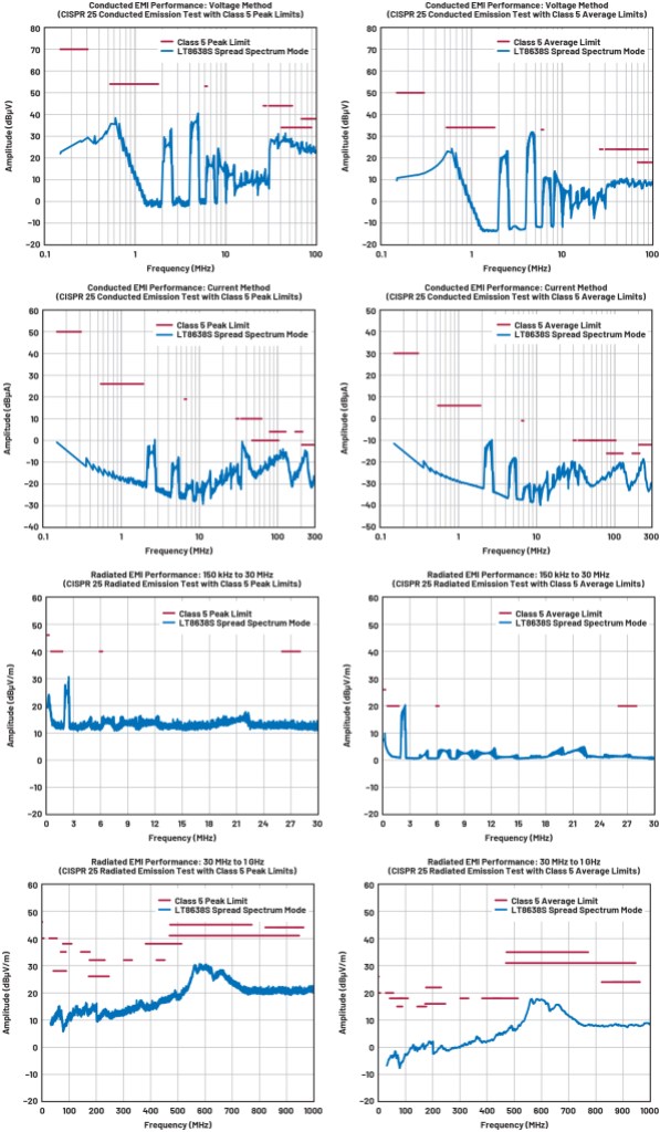
Figure 5 shows the LT8638S emissions of the Figure 4 circuit, with the test setup defined in the CISPR 25 standard. The red lines represent CISPR 25 Class 5 limits, which are the most stringent emission specifications in automotive industry. With very few additional components generating an input filter, as shown in Figure 4, the LT8638S can meet CISPR 25 Class 5’s stringent peak and average limits.

Figure 5: Radiated EMI and conducted EMI of the Figure 4 circuit (12-V input to 3.3-V output at 10 A) (Source: Analog Devices)
Higher-current monolithic power solution using the LT8648S
A complex ADAS requires more than one SoC, along with several cameras and sensors. For instance, a hands-free ADAS could include multiple power-hungry chips and up to 11 cameras. The LT8648S has higher output current capability than the LT8638S. It fits into the intermediate power rail required by a complicated ADAS. As a monolithic 42-V, 15-A buck regulator, the output current and power level of the LT8648S are close to a power controller solution using external MOSFETs. Its current capability can be further extended by paralleling several LT8648S regulators together.
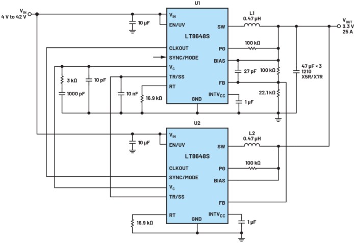
Figure 6 demonstrates 3.3-V/25-A, 2-MHz schematics using two LT8648S devices in parallel. The two LT8648S regulators have a common input and output. The EN/UV and SS pins are connected to ensure that the two regulators start up simultaneously with the same slew rate. The LT8648S uses peak-current mode control, which makes the error amplifier output VC voltage correlated with the load current. By connecting VC and FB pins, the two parallel LT8648S devices can achieve good current balancing without the need for an extra circuit. The CLKOUT pin of the U1 LT8648S is connected to the SYNC/MODE pin of the U2 LT8648S. With this connection, two LT8648S regulators are synchronized with 180˚ phase shift.

Figure 6: A 2-MHz, 3.3-V/25-A application using two LT8648S regulators in parallel (Source: Analog Devices)
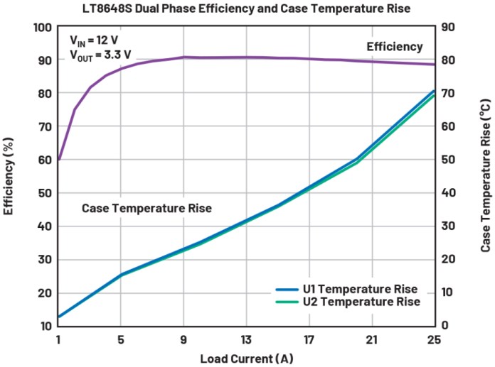
Figure 7 shows the efficiency and temperature rise of the Figure 6 circuit. U1 and U2 have almost the same temperature, which indicates good current balancing in this parallel application. High switching frequency and external compensation enable the fast transient response.

Figure 7: The efficiency and temperature rise of the circuit shown in Figure 6 (Source: Analog Devices)
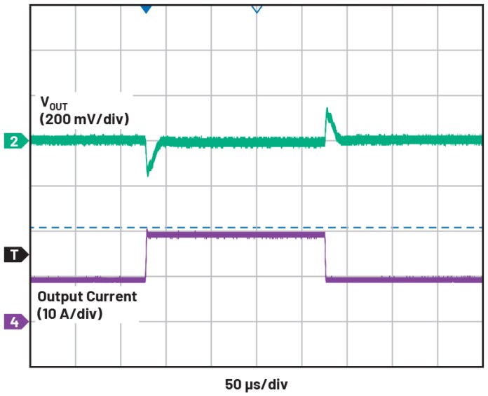
Figure 8 shows the load transient response of the circuit shown in Figure 6.

Figure 8: 10-A to 20-A load transient response of the circuit shown in Figure 6 (Source: Analog Devices)
Conclusion
This article introduces two high-current 42-V monolithic Silent Switcher regulators, the LT8638S and LT8648S. Their great efficiencies and ultra-low emissions alleviate the thermal and EMI concerns in harsh automotive application environments. With integrated MOSFETs, the LT8638S and LT8648S regulators offer a small solution size for the high-current intermediate power supplies required by rapidly expanding automotive ADAS applications.
About the author
 Ying Cheng is a staff applications engineer for power products in the Industrial and Multimarkets Business Group at Analog Devices in Santa Clara, California. She has been working at ADI since 2010. She currently provides application support for non-isolated monolithic step-down converters. Ying Cheng’s interests in power management include high-performance power converters and regulators with high efficiency, high power density, and low EMI for automotive, telecom, medical, and industrial applications. She received B.S.E.E. and M.S. degrees from Shanghai Jiao Tong University, China, and obtained a Ph.D. degree in electrical engineering from Missouri University of Science and Technology (formerly University of Missouri–Rolla) in Rolla, Missouri. She can be reached at ying.cheng@analog.com.
Advertisement
Learn more about Analog Devices


