I like to think of engineers as doctors of the electronics world. Let me explain: Think about the last time an optometrist examined your “human sensors.” Did they prescribe glasses to compensate for drift in vision that occurred over time? Did your otolaryngologist amplify your hearing by cleaning out your ears or providing a hearing-aid device? Doctors help keep sensory organs (eyes, ears, nose, tongue, skin) working properly and make sure that the data those organs capture is reliably transmitted to the brain through the nervous system. If you translate this sensory feedback loop to the electronics world, engineers designing real-time control systems ensure that sensors work properly and that the data those sensors capture is reliably transmitted to the processor across the analog signal chain.
As illustrated in Figure 1, real-time control (RTC) is the ability of a closed-loop system to gather data, process that data, and update its output within a defined time window. In this article, I’ll focus on the first functional block of real-time control systems — sensing (gathering) data.
I’ll discuss three sensor parameters that you should keep in mind when optimizing your data capture and explain how additional integrated circuits (ICs) in your signal chain may enable you to have more customization to best match each circuit’s specific needs.
Real-time control systems are all around us, often collaborating with humans and being directly responsible for their safety. That’s why engineers consider many variables that can affect a system’s performance over time and across various conditions.
Whether you are monitoring the position and speed of a motor, regulating the current draw of an electric vehicle (EV) charging station, or even measuring the closing distance between a vehicle and a car stopped ahead of it, proper sensor selection for a successful feedback loop is a priority. The most important variables for the safety and performance of real-time control are a sensor’s speed, accuracy, and reliability.
Selecting the sensor
Choose a sensor that gathers and communicates data within your defined time window.
Applications in which the environment changes rapidly need a sensor that can respond to these changes and communicate data quickly. The faster a system can gather and process sensor data, the quicker it can update its outputs to maintain stability and efficiency.
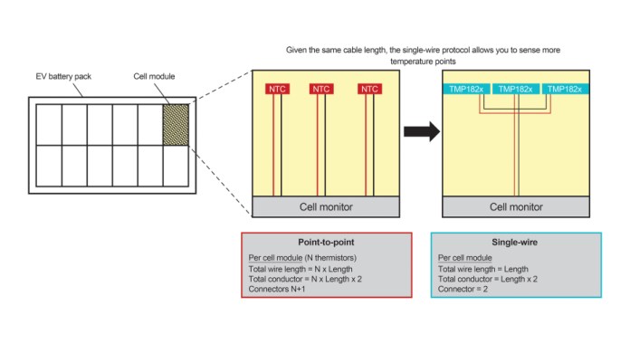
Let’s take a look at EV battery packs, where there are over 30 temperature sensors scattered across battery cells to safely operate the battery pack and optimize charging. The challenge here is that adding more temperature sensors requires more cables, adding more weight to the vehicle and reducing its efficiency.
To continue monitoring the same number or even more temperature points while reducing the amount of cabling needed and weight, consider adopting the single-wire communication protocol, as shown in Figure 2, which shows a decentralized cell-monitoring scheme with a cell supervisor board for each module. If you use a centralized monitoring architecture where there is only one board for the whole battery pack, then the impact of switching from point to point to single wire is greater, saving even more cable weight and cost.

Figure 2: Reducing EV battery temperature sensor cabling in a decentralized cell-monitoring topology (Source Texas Instruments Inc.)
When there are many sensors on one bus, it’s important to make sure that the communication speed is fast enough for the controller to query a new temperature reading from every single sensor, all within a defined time window. Devices such as the TMP1826 from Texas Instruments (TI) support both standard speed for legacy applications and an overdrive mode with a 90-kbps data rate for low-latency communication, enabling the real-time control systems to update each battery module’s temperature points fast enough.
Choose an accurate sensor and follow best practices to minimize external errors.
To achieve precise feedback from sensors in real-time control systems, it’s important to use an accurate sensor and follow mechanical and software best practices when designing it in. Consider a motor-controlled system such as six-axis robotic arms and collaborative robots (cobots), as shown in Figure 3. These robots require accurate motor position sensing and control to ensure exactness in assembly processes and safety where there is human interaction.
The more accurate your position sensor is, the more flexibility in your magnetic and mechanical design. A precision Hall-effect position sensor such as TI’s TMAG5170 has sensing speeds as high as 20 ksps and a maximum total error of 2.6%, enabling you to accurately monitor a motor’s position while quickly responding to any angular changes.
But in order to achieve accurate measurements for your specific application, it’s not enough to simply choose the most accurate sensor you can find. I recommend that you also follow design best practices and consider all possible error sources such as mechanical imperfections of the system or errors related to the signal chain. For real-time control systems requiring precise angular feedback in magnetically sensed applications, follow the guidelines found in the “Achieving Highest System Angle Sensing Accuracy” application note.

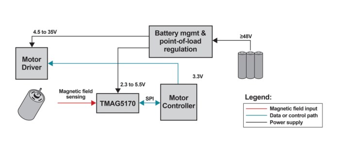
Figure 4: Sensing and actuating a motor with a real-time control system (Source Texas Instruments Inc.)
Using a fast and accurate sensor while following best design practices is critical, but you still need to communicate and process its data reliably for a robust real-time control system. Figure 4 illustrates a feedback loop from a position sensor (sensing) to the motor controller (processing) and finally to the motor driver (actuation). Because these signals will move in and out of multiple ICs across your PCB, it’s important to design your power stage with electromagnetic interference (EMI) in mind to minimize its interference and maintain proper data reliability in noisy environments.
Choose a sensor qualified to the standards that cover your product’s mission profile.
A mission profile is a description of all the load conditions and environmental stresses a product may be exposed to across its lifespan, and it can vary a lot depending on the market and geographic location of operation. For example, a vehicle designed for use in Greenland must be able to withstand much colder temperatures than one designed for use in Qatar. To ensure that your real-time control system works properly across its lifespan and extreme conditions, it’s important to make sure that the components you use in your end product have been qualified to standards that meet your product type and mission profile.
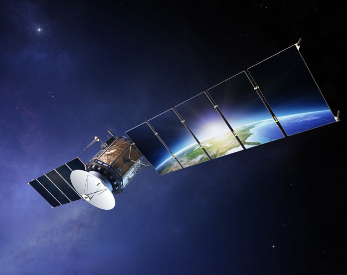
A great example of this can be found in the thorough chip selection process for satellites in space. For example, the ICs found in a satellite like the one shown in Figure 5 not only need to withstand intense physical vibrations and large amounts of radiation but also extreme temperature variation.

Figure 5: Space is a particularly harsh environment for electronic components. (Source: Texas Instruments Inc.)
One example of real-time control in space is found on the power generation and distribution systems in satellites that use current-sense amplifiers (CSAs) to monitor their main power rail input current to detect single-event transients. If an overcurrent event is detected, the processor can react in real time to shut down electronic subsystems and prevent damage.
Technology advancements like space-enhanced plastics and radiation-hardened packaging are leveraged in CSA products like the INA901-SP and INA240-SEP to maintain highly accurate measurements and enable real-time control in space. To learn more, check out “How current-sense amplifiers monitor satellite health.”
Level up your sensing signal chain for RTC
Not all real-time control systems are created equal. When you need additional flexibility to fine-tune certain aspects of your data capture, that’s when adding extra components to your signal chain can make a huge difference.
Take, for example, LiDAR systems used in autonomous driving. This real-time control system must refresh extremely fast so that the vehicle can continue driving or slam on the brakes based on the environment sensed ahead of it. The challenge LiDAR designers face is that they want to accurately sense further distances. This would require a higher-amplitude laser beam, but eye safety standards limit the maximum power that is able to be transmitted in a pulse.
So a workaround is that you can transmit shorter pulses at higher amplitudes to travel longer distances while maintaining the power levels within safety limits. However, to do this would require a much faster detection of those pulses on the receiver side, and that’s where additional devices in your data capture signal chain come into play, such as high-speed comparators.

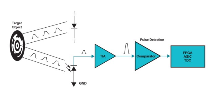
Figure 6: A high-speed comparator can boost the performance of LiDAR designs. (Source: Texas Instruments Inc.)
As seen in Figure 6, a high-speed comparator like the TLV3801 translates the analog pulse received to a digital format and interfaces to the downstream controller. The low variation in propagation delay and ability to detect narrow pulses makes the TLV3801 an excellent choice for time-of-flight (ToF) designers looking to detect further distances using LiDAR. For more information on this application, check out the “How to Improve Accuracy with High-Speed Comparators in LIDAR and Proximity Sensing” app note.
Another common device that receives the output of a sensor in a real-time control signal chain is an isolator. Although their use is application-dependent, isolators provide the necessary protection to maintain proper data capture in high-voltage circuits and prevent that high voltage from crossing over to the low-voltage side. Not only can an isolator protect the processor from damage, but it can also get rid of ground noise to improve signal quality.
Adding an isolator offers flexibility advantages in the number of data channels available, the level of isolation required to be met, and the type of output sent to the real-time control processor. To develop your expertise on isolators and their essential parameters such as isolation ratings, common-mode transient immunity (CMTI), and more, check out the isolator training videos on TI’s Precision Labs.
Conclusion
Sensing often refers to the measurement of external variables, such as voltage, current, motor speed, position, humidity, and temperature. A sensor’s response time, communication speed, accuracy, and reliability are key parameters that affect the circuit’s ability to send dynamic data to the control system in real time. It’s easy to forget that the signal chain does not consist only of a standalone sensor. Discrete ICs like comparators, isolators, and many others enable more customization to best match each specific circuit’s needs in your real-time control system.
Advertisement
Learn more about Texas Instruments


