When you’re designing miniature optical switches, reflective sensors are your best friend. They streamline the interaction between humans and machines in an elegant and intuitive manner. These sensors, typically concealed behind infrared (IR) transmissive covers, spring into action when a finger or another object touches the surface of the cover.
Optical sensors, or reflective sensors, simplify the process of designing a button that feels intuitively smart and operates reliably. The mechanism is as straightforward as it is efficient:
- The sensor houses an emitter that throws out IR light on one side.
- When a finger or any object draws near, it’s illuminated by this light.
- The reflected signal creates a photocurrent at the detector situated on the other side.
These sensors work invisibly, with no moving parts or friction, and they have virtually no wear and tear. What’s more, optical sensors can be tweaked and fine-tuned to tackle moisture, water, dirt and scratches on the cover surface. They perform just as effectively with gloves on.
Do bear in mind that like any sensor integrated into an application, there are crucial challenges to consider to ensure everything functions as planned. For optical sensors, these are primarily environmental and mechanical hurdles within the application housing.
Environmental challenges
Imagine this: You’re dealing with ambient noise at the detector caused by external interference like sunlight and typical light sources. Now, let’s consider the offset current created by reflections from the surrounding aperture, dirt, water, moisture or scratches on the cover’s surface. This offset adds to the proximity signal, increasing the total amplitude of the output signal.
If you don’t address these factors during the design phase, the intensity of the noise signal might increase to the point where it exceeds a set threshold, leading to false detections. To prevent this, you should aim to design the sensor in a way that minimizes these environmental influences, thereby maintaining a healthy signal-to-noise ratio.
Mechanical challenges
For the sake of aesthetics, you’ll typically find sensors tucked away under IR transmissive covers, or the viewing-hole size of an optical sensor might need to be kept to a minimum.
Plus, to make room for multiple buttons situated closely together, the sensor should occupy the smallest possible space. This scenario results in stringent mechanical constraints for the sensor’s package dimensions on one side and exacting requirements for the angular emission/viewing characteristics on the other.
Use cases
Now that you understand the environmental and mechanical challenges involved in designing optical switches with reflective sensors, let’s delve into three specific use cases.
An automotive touch switch that works under direct sunlight
Optical sensor buttons can fit anywhere in a car due to their compact size. However, to deal with the variable conditions in a vehicle, high standards of reliability are necessary. Factors like temperature fluctuations and the influence of sunlight also need to be considered.
The sensor can be safeguarded and correctly oriented with an optimized aperture to shield it from disruptive sunlight. Moreover, the sensor package can be designed to eliminate all troublesome light wavelengths. This means that the sensor only responds to light in the wavelength range of the emitter, already filtering out a substantial portion of ambient noise.
You can further enhance the sensor with DC light-suppression circuitry and a high-pass filter at the detector, as depicted in Figure 1. This arrangement ensures that only the pulsed emitter signal gets detected and amplified.

Figure 1: DC light-suppression circuitry and a high-pass filter at the detector (Source: Vishay Intertechnology)
An optical button panel in a confined space
When your design requires the implementation of multiple buttons in a limited space, a sensor featuring an emitter that leverages a vertical-cavity surface-emitting laser (VCSEL) with high radiant intensity and a powerful optical output is an excellent fit.
The VCSEL’s narrow emission angle considerably diminishes the offset caused by a cover, making the sensor especially well-suited for operation under transparent materials. Additionally, the radiation pattern and compact dimensions of the sensor allow for extremely tight side-by-side placement—so tight, in fact, that the breadth of a finger becomes the limiting factor. Thanks to the radiation pattern of the VCSEL, you can find a sweet spot for the cover where it produces only a minimal offset. This sweet spot is best determined from a distance curve.
A distance curve (Figure 2) demonstrates the relative output signal of the sensor versus the distance of a mirror or cover glass. The signal stays sufficiently low up to a distance of roughly 2 mm. This suggests that a cover glass should ideally be maintained within this range, up to a distance of 2 mm, to keep the offset to a minimum, thereby enhancing the signal-to-noise ratio, as discussed above.
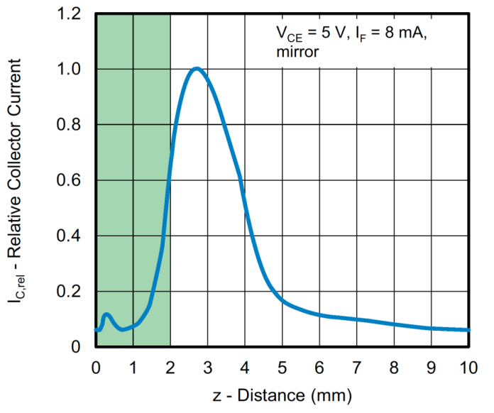
Figure 2: A distance curve demonstrates the relative output signal of the sensor versus the distance of a mirror or cover glass. (Source: Vishay Intertechnology)
A button for harsh industrial or medical environments
Let’s suppose your goal is to design a button that’s robust and suitable for harsh industrial or medical applications. An optical button would simplify cleaning, as its smooth surface has no crevices for dirt to infiltrate. However, it’s essential that the sensor doesn’t get triggered by liquids or dirt. Rather, it should register a press even if the finger is positioned imprecisely and not directly over the sensor.
The optical button’s sensitivity to surface contaminations on the cover is reduced due to the IR emitter’s wide emission angle. This broad emission allows radiation power to be distributed over a larger area. Additionally, this wider emission facilitates the detection of fingers not placed directly over the sensor. Importantly, gloves, frequently used in such environments, don’t pose a problem and are detected by the sensor just as easily.

Figure 3: Simplified button design application (Source: Vishay Intertechnology)
The model shown in Figure 3 illustrates a simplified real-world application of a button design that meets these criteria. The sensor operates under a 2-mm–thick, IR-transmissive, polycarbonate cover positioned 3 mm from the sensor’s top. The aperture is designed large enough for the wide emission angle of the sensor to minimize offset noise.
To make it insensitive to sunlight, the circuit topology depicted in Figure 1 is employed. The emitter is pulsed at 5 kHz. An additional high-pass filter is designed so that the cutoff frequency is below this frequency but effectively dampens the typical mains hum at 50 Hz.
The output signal can be directly linked to an analog-to-digital converter for further processing. A calibration routine allows the sensor to disregard offsets caused by the aperture. This results in an extraordinarily robust design that’s highly resistant to false triggers due to external factors, making it incredibly reliable.
Advertisement
Learn more about Vishay Intertechnology


