For better spectrum use, Long Term Evolution (LTE) systems must employ multiple-input, multiple-output radios in special ways
BY JAN WHITACRE
Agilent Technologies
Santa Clara, CA
http://www.agilent.com
Increasing use of high-bandwidth applications (such as streaming video) drives a continued desire for higher throughput or better coverage from wireless systems. Changing the use of the spectrum available is being pursued through several approaches.
Release 8 of the 3GPP specifications, which specifies the Long Term Evolution (LTE) toward fourth-generation (4G) systems, includes new requirements for operation, where a base station and handset communicate using two or more transmit/receive chains, and takes advantage of the differences in radio transmission paths between them. The goal is to increase both overall capacity of a cell and the data rate that a single user can expect from the system.
Fundamental changes
LTE requires fundamental changes in base station and handset design and test due to the higher data rates, wider allowable signal bandwidths, and increasing integration and miniaturization in the handset. For example, equipment must handle six different channel bandwidths from 1.4 to 20 MHz and both frequency- and time-division-duplex (FDD and TDD) modes.
Also, an LTE handset must support legacy systems right back to basic GSM or cdma2000, depending on the network genealogy, and be able to transfer seamlessly among them. Handset components complying with the multi-gigabit DigRF v4 standard, which removes the potential communication bottleneck between the baseband and RF ICs, require cross-domain (digital-in, analog-out) measurement capability.
LTE testing requires a digital test source, which must emulate both data traffic and the encapsulated protocol stack within the digital interface that controls RF IC functionality. And information transfers between the handset RF and baseband ICs must comply with strict timing constraints.
Added to these general issues are the specific challenges resulting from the need to support multiantenna techniques. Five such techniques have been defined for LTE to improve link performance:
Receive diversity at the mobile device.Transmit diversity using space/frequency block coding (SFBC) at the base station (referred to in LTE specifications as evolved Node B, or eNB).MIMO spatial multiplexing at the eNB, for one or two users.Cyclic Delay Diversity (CDD) at the eNB, used in conjunction with spatial multiplexing.Beam steering (user specific).
The first two techniques are relatively conventional diversity methods. The third and fourth methods make use of space-frequency coding mechanisms to spread data across multiple antennas. Cyclic delay diversity introduces deliberate delays between the antennas to create artificial multipath. The techniques are applied differently, depending on the type of physical signal or physical channel.
Conventional phased-array beam steering introduces phase and amplitude offsets to the whole of the signal feeding each transmitting antenna, with the intention of focusing the signal power in a particular direction. The same technique of applying phase and amplitude offsets can be used on the receiving antennas to make the receiver more sensitive to signals coming from a particular direction.
Multiple-input, multiple-output (MIMO) radios get more from the RF bandwidth they occupy than their single-channel equivalents by exploiting differences in the paths between the transmitter and the receiver inputs. If a conventional single-channel radio system creates one data “pipe” between the transmitter and the receiver, the object of a MIMO radio system is to create multiple pipes. It does this by creating a mathematical model of the paths from transmitters to receivers, and solving the resulting equations. There have to be as many equations as there are unknowns, and the equations need to be solved in real time, as fast as the channel is changing.
Inputs and outputs
In the specifications, the terms “input” and “output” apply to the medium between the transmitters and receivers, including the RF components of both known as the “channel.” Thus a base station with two transmitters provides two inputs to the channel – the “MI” part—and a handset with two receive chains takes two outputs from the channel – the “MO” part. This is true only if the data transmitted and received is independent, and is not just a copy of the same data, as explained below.
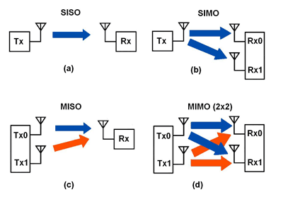
Fig. 1. Four input/output combinations are possible.
Single input, single output (SISO) is the standard transmission mode in most systems (Fig. 1a ). The objective of any more-complex system is to increase capacity, or data rate, as measured with respect to SISO.
Single input, multiple output (SIMO, Fg. 1b ) is a receive-diversity technique. A single transmitter, and therefore a single data stream, feeds two receiver chains. This aids received-data integrity, a particular plus where signal to noise ratio is poor due to multipath fading. There is no gain in data capacity except any benefit that comes from better error ratio and consequent reduced retransmission.
Similarly, multiple input, single output (MISO, Fig. 1c ) is a transmit diversity technique. In LTE, space / frequency block coding is used to improve signal robustness under fading conditions. The transmitters send the same underlying user data, but in different parts of the RF space.
True multiple input, multiple output (MIMO, Fig. 1d ), with two transmitters and two receivers with independent data content, is also known as spatial multiplexing. Each receiver sees the output of the channel, which is a combination of the outputs from the transmitters. Using channel estimation techniques, the receivers use matrix mathematics to separate the two data streams and demodulate the data.
In ideal conditions, data capacity would be doubled with MIMO, though there is a premium to be paid in a better signal-to-noise-ratio requirement than for SISO. Practically, the doubling of data capacity is never achieved, but definite increases can be seen.
The MIMO channel
Consider an instant in time at a single frequency and model the channel as a black box with fixed components inside. If we add two completely different signals at the input, they will be mixed together in a defined way, depending on the values of Z1 to Z4 (Fig. 2 ). If we send a training signal that’s unique to each input and measure the outputs we know how they got coupled, and therefore how to uncouple them.
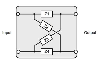
Fig. 2. The values of Z1 through Z4 determine how signals are mixed.
In LTE, reference signals (or pilots) at regular frequency locations in the output of each transmitter provide a way for the receivers to estimate the channel coefficients. Everything, data and reference signals, will be coupled in the same way, so what we learned from the reference signals can be applied to real data. Noise and interference limit the modulation that can be used, along with the ability to uncouple the outputs.
The worst case would be if Z1 to Z4 are all the same, when both outputs would be the same and MIMO would not work. The best case is if the outputs are equal in magnitude and opposite in phase, when capacity would theoretically double.
The terms “code word,” “layer,” “precoding,” and “beam forming” have been adapted specifically for LTE to refer to signals and their processing (Fig. 3 ).
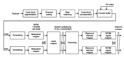
Fig. 3. Signals are processed in multiple stages for LTE.
A code word represents user data before it is formatted for transmission. One or two code words, CW0 and CW1, can be used depending on the prevailing channel conditions and use case. In the most common case of single-user MIMO (SU-MIMO), two code words are sent to a single handset (commonly referred to as user equipment, or UE), but in the case of the less common downlink multi-user MIMO (MU-MIMO), each code word is sent to only one UE.
The term “layer” is synonymous with “stream.” For MIMO, at least two layers must be used. Up to four are allowed. The number of layers is always less than or equal to the number of antennas.
Precoding modifies the layer signals before transmission. This may be done for diversity, beam steering, or spatial multiplexing. The MIMO channel conditions may favor one layer (data stream) over another. If the base station (eNB) is given information about the channel — for example, information sent back from the UE — it can add complex cross-coupling to counteract the imbalance in the channel. In a 2×2 arrangement, LTE uses a simple 1-of-3 precoding choice, which improves performance if the channel is not changing too fast.
Eigen beam forming (typically known simply as beam forming) modifies the transmit signals to give the best CINR at the output of the channel.
In LTE specifications, the symbols d, x, and y are used to denote signals before layer mapping, after layer mapping, and after precoding, respectively.
SU and MU-MIMO usage
Both code words are typically used for a single user in the downlink (Fig. 4 ). It is also possible for the code words to be allocated to different users to create MU-MIMO.
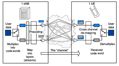
Fig. 4. A downlink uses both code words to transmit to a single user.
Depending on the channel information available at the eNB, the modulation and the precoding of the layers may be different to equalize the performance.
Uplink SU-MIMO is within the scope of LTE, but is not a development priority for various reasons, including UE cost and battery constraints. Although a UE typically has a single transmitter, it nevertheless is still capable of supporting a novel form of MIMO. MIMO does not require that the transmitters are in the same physical device or location, which it does for the receive function. Thus uplink MIMO can be implemented using two transmitters belonging to two different UEs (Fig. 5 ).
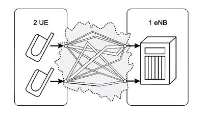
Fig. 5. Uplink MIMO with transmitters in separate UEs.
This creates the potential for an increase in uplink capacity, although an individual user will see no increase in data rate.■
Advertisement
Learn more about Agilent Technologies


