By SHERI DeTOMASI, Product Manager
Keysight Technologies*
www.keysight.com
With the increased complexity in RF components used in such wireless products as cellular phones, tablets, and wireless routers, design engineers are under increasing pressure to add more functionality while keeping design and manufacturing costs low. Selection of test equipment/software can impact the performance and efficiency of the wireless device design as well as the cost to produce the device.
The following paragraphs outline the three common challenges designer are facing, and then provide a week’s worth of tips to help design validation and manufacturing test teams select hardware and software that will accelerate design, increase test throughput, and ultimately lower the cost of test.
Test Challenges
New multi-radio and multi-function devices are requiring wider transmission bandwidths, more complex modulation schemes, and even multiple transmit and receive chains, which significantly increases device complex¬ity and test needed to verify the device’s performance. The following are some typical challenges faced by RF device test engineers.
CHALLENGE 1: Increasing device complexity
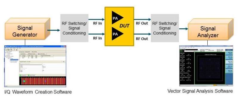
A typical manufacturing test setup (see fig. 1 ) for a power amplifier (PA) enables a test engineer to quickly determine if the device under test (DUT) meets the required modulation performance at the desired power level. Note that switching and signal conditioning is often used either internal or external to the device to support testing of multiple-frequency-band PA modules.
Today, many new PAs support multiple operating modes in addition to multiband capability; the added modes allow for higher performance in end-user equipment. As the complexity of the PAs increases, the ability to get high quality signals through the additional switching and signal conditioning becomes more difficult.

Fig. 1: In this simplified power-amplifier-test block diagram, a vector signal generator (VSG) is connected to the DUT through cabling, switching, and signal conditioning.
CHALLENGE 2: Reduce test time
Reducing test time by even a few milliseconds can have a significant impact on the cost of test., While multi-radio tests can take anywhere from hours to days during design validation, in manufacturing seconds count.
Consider that a typical PA manufacturing test includes the time it takes to adjust the modulated input power from the signal generator to get the desired output level from the DUT. This is typically done in the power- servo loop test: a control loop that is used to determine the final gain of the PA. That is, after the DUT output level is measured by the signal analyzer, the new value of the output power is calculated based on the difference between the measured power and the desired power. The signal generator is then adjusted to the necessary output power to achieve the correct output power from the DUT. Only after the DUT output level is set to the correct value can the specified parameters be tested.
The time spent adjusting the signal generator to get the correct DUT output power can be one of the major contributors to overall test time, which increases the overall cost of test.
CHALLENGE 3: Scalable instrumentation for multi-channel measurements
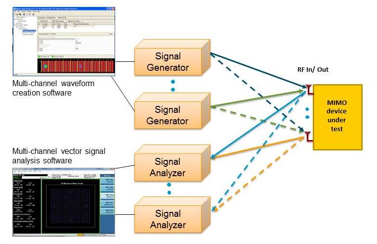
Newer wireless designs implement multi-antenna techniques like carrier aggregation and MIMO to increase data throughput and cell capacity. Testing these designs often requires multiple signal generators and/or signal analyzers to simulate and analyze the multi-antenna signals (see fig. 2 ). This test setup gets very complicated and requires multichannel synchronization and new measurement techniques that allow for the hardware and software to demodulate and analyze the multiple data streams simultaneously.

Fig. 2: Multiantenna testing typically requires multichannel signal generation for receiver test or multichannel signal analysis for transmitter tests.
A Week’s Worth of Test Tips
MONDAY
Select a signal generator with good modulation performance, even at high output power levels, so the highest quality signal can be delivered to the DUT
Many PAs require that the digitally modulated input signal, such as LTE, be at an input power level of 0 to +5 dBm. By using a signal generator that can output signals as high as +15 dBm, you can overcome any losses between the signal generator and the DUT that may arise due to switching or other signal conditioning.
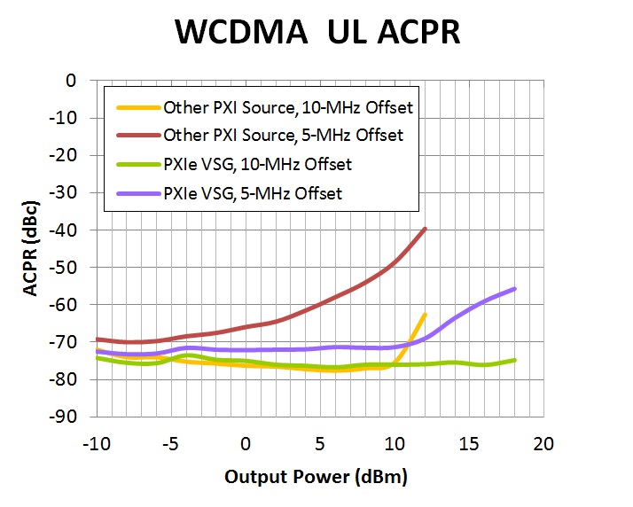
Consider the adjacent channel power (ACPR) measurement made using high power outputs from two different sources, one of which is a PXIe vector signal generator (VSG) with excellent modulation performance (fig. 3). For the PXIe VSG, at +10 dBm, there is little to no degrading of the ACPR, and at +15 dBm the ACPR is still near 60 dBc.

Fig. 3: For ACPR measurement at high power, some new PXIe VSGs can provide digitally modulated signals up to +19 dBm output power with ±0.4 dB level accuracy, resulting in the highest quality signal being delivered to the DUT at a lower cost.
TUESDAY
Select instruments with fast measurement speed to reduce test time and lower the cost of test
A signal generator with fast frequency and amplitude switching time enables quick modulated input power adjustments to get the desired output level from the device under test. When the output level of the signal generator cannot be predetermined for use with list mode, having rapid frequency and amplitude switching speeds — along with superior linearity, repeatability, and resolution specifications — will significantly shorten the time it takes to converge on a desired output power and to reduce test time and the overall cost of test.
On the measurement side, selecting a signal analyzer that can perform power, ACPR, EVM, and harmonics tests quickly and accurately, and that can switch between different measurements in minimal time, will ensure that accuracy is not sacrificed for speed.
Power measurements with some newer PXIe vector signal analyzers (VSAs) can be captured in the analyzer’s digitizer in real time and returned as a single measurement value to the application program. No additional computation of the power measurement is required in the controlling PC.
These VSAs provide power measurements with acquisition times from 10 µs to 1 ms. When combined with the power-level switching speed of the PXIe VSG, the step time for a power servo loop test can be less than 1 ms, dramatically reducing the amount of time it takes to converge on the desired output power level in the servo test. Reducing test time increases device test throughput, and the per-device cost of testing goes down..
WEDNESDAY
Select a flexible platform that easily incorporates different instruments for testing throughout the product lifecycle
In the design or design-validation phase of the product development cycle, it may be necessary to look at the RF device’s performance out-of-band. Any harmonics or spurs generated by the device can affect the quality of the output signal. If out-of- band signals are present, this can cause interference in the wireless network and compliance issues with FCC regulations.
Thus, it’s helpful to have the flexibility to include signal analyzers with higher frequency ranges earlier in the design phase to measure out-of-band spurs and harmonics. If, for example, the device supports LTE bands 40/41, the design engineer may want a signal analyzer that that can measure the 3rd harmonic up to 8.1 GHz, or even the 7th harmonic up to 19 GHz. Once the product moves to manufacturing, a lower-frequency, lower-cost signal analyzer may be used.
THURSDAY
Select test equipment that uses the same measurement software — from R&D to manufacturing — for consistent, reliable test-result validation
When traditional benchtop and PXI instruments are used for device test, use of common software with the same measurement algorithms and measurement science will ensure consistent, reliable results, regardless of instrument form factor. For example, measurements made in the lab with benchtop equipment can be quickly validated on PXI instruments in a manufacturing test environment. The ability to use the same programming commands and a consistent user interface allows for consistent measurement results and further reduces test development time.
FRIDAY
Select test equipment that has warranted specifications for greater measurement integrity
Poor measurement integrity can lead to test “escapes” (failure to detect a fault) or the opposite, false failures, for the devices under test, which increase repair costs and can lead to higher overall manufacturing costs, not to mention damage to a company’s reputation and productivity.
Calibration directly impacts measurement quality: an instrument’s specifications are guaranteed through calibration. PXI instruments may be calibrated at the individual module level or as a bundle of multiple modules when they are combined to make a single instrument, such as a PXIe VSA. Some vendors only calibrate individual modules. When this is done, it is very difficult to specify warranted, instrument-level specifications. It is important that the test equipment selected include calibration routines at an instrument level to guarantee a higher level of measurement performance.
SATURDAY
Select a test platform to minimize system downtime
Supportability and quick repair turnaround times (TAT) are critical factors in keeping a system up and running. It can be very costly when unplanned maintenance or equipment failures are encountered in manufacturing or in critical R&D applications.
Just one test system unexpectedly going down for repair can have a devastating impact on DUT shipments. In addition, the cost for repairs, re-calibration after repair, and re-installation into the system adds up quickly. Be sure to select test equipment that has low meantime between failures, fast TATs, and longer product warranties.
SUNDAY
Select a test platform that is scalable for future needs… and take a rest
We live in a dynamic world. Wireless standards continue to evolve with wider bandwidths, more antennas and greater synchronization needs — and test equipment needs to support new standards and test requirements. Selecting a PXI or AXIe platform that can evolve as standards and test requirements evolve can help future-proof a test system.
Some companies offer license key upgrades for hardware options to let engineers keep their equipment operational, in house. Be sure to select equipment that is easily upgraded later as test requirements change.
—————————————————-
*Keysight Technologies Inc.is the former Agilent Technologies electronic measurement business.
Advertisement
Learn more about Keysight Technologies, Inc.


