By SungJin Kuen, iFET Applications Engineer,
Fairchild Semiconductor
www.fairchildsemi.com
Bridge rectifier circuits used at the power input of a device allow it to be insensitive to the polarity of the device’s power source. The device itself may be sensitive to the polarity of the power source, but the bridge rectifier can be configured to provide the proper polarity to the device when the polarity of the power source is reversed. Some systems, such as Power over Ethernet (PoE) Powered Devices (PD), have specifications that require them to operate properly in the event of a reversal in polarity. This type of bridge rectifier circuit is intended to correct polarity mismatch and not to rectify AC power.
A bridge rectifier can be configured using standard diodes; however, these rectifier circuits have relatively high energy losses as:
Power loss of diode bridge = 2 x VF x IIN
An active MOSFET bridge addresses this drawback using MOSFETs to implement the bridge configuration, as Fig. 1 shows.
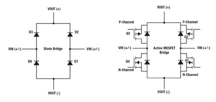
Fig. 1: Diode bridge vs. active MOSFET bridge rectifier.
The calculation for the power loss of an active MOSFET bridge is IIN 2 x (P-ch_RDS(ON) + N-ch_RDS(ON) ). If the input current is 1 A, the power loss of the active MOSFET bridge is just 0.169 W, with 169-mΩ total conduction resistance — the sum of P- and N-channel RDS(ON) . This compares to a 1.4-W loss for the diode bridge, assuming 0.7-V diode forward voltage. The difference is substantial.
When implementing the active MOSFET bridge, the major consideration is the gate driving circuits to turn on the diagonal MOSFETs according to the polarity of the power source, which can be relatively costly and consume valuable PCB space. When the active MOSFET bridge is used in a PoE PD application, the IEEE 802.3at PoE standard has to be considered and adhered to in most cases.
It is important for designers to understand the detection and classification procedures defined by the 802.3at PoE standard. These include a requirement for the power source equipment (PSE) to recognize if the PD is available and how much power the PD consumes when connected to the PSE via the network cable. During the resistance detection period, the PSE delivers two consecutive voltages — V1 = 2.7 V and V2 = 10.1 V — and then records the measured currents with the PD presenting 25 KΩ. If the computed ∆V/∆I equals 25 KΩ, with tolerance from 23.7 KΩ to 26.3 KΩ, the PSE ensures the presence of a PD.
The PSE then moves to the power-classification mode to identify the PD power class using the same method. The PSE provides a single voltage in a range from 14.5 V to 20.5 V and then measures the current to calculate the present resistance. Using the computed resistance, the PSE recognizes the PD power class. During these two stages, the active MOSFET bridge circuit must maintain low-current consumption and not interfere with the 25-KΩ resistance detection and power classification. That is one reason the active MOSFET bridge needs the optimized gate driving circuits. Fig. 2 illustrates the simplified PoE system diagram and the current path from PSE to PD during both procedures.
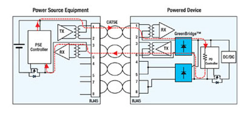
Fig. 2: A PoE system diagram.
There are a number of ICs available to control a MOSFET bridge. A better choice may be a fully integrated bridge solution like Fairchild’s GreenBridge FDMQ8205. The chip’s 80-V MOSFETs in a full bridge topology use patented gate driving circuits in a single 4.5 x 5.0-mm MLP package. Fig. 3 illustrates a PoE PD application diagram with dual FDMQ8205 ICs.
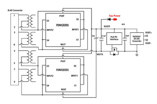
Fig. 3: PoE PD application diagram.
This PoE system supports two types of PSE (power source equipment): the End-Span PSE and Mid-Span PSE. An End-Span version delivers the data and power together using the 1, 2, 3, and 6 pins in the network cable. A Mid-Span PSE, on the other hand, supplies the power via the 4, 5, 7, and 8 pins and uses the 1, 2, 3, and 6 pins for the data. Because of this, the IEEE 802.3at PoE standard requires that two bridges be used in PoE PD applications to cover the two types of PSE.
Advertisement
Learn more about Fairchild Semiconductor


