Adaptive loop regulation state-of-the-art performance
The challenge of contemporary systems is to avoid the duplication of overhead components
BY MAURIZIO SALATO
Vicor, Andover, MA
http://www.vicorpower.com
Traditionally, design of the power supply for complex electronic systems (telecom, ATE, computing, solid-state lighting) was not a critical element. Power was a commercial off-the-shelf (COTS) item, readily available and affordable. The number of outputs and total power available were limited, so the critical decision on power design was simply choosing the right connector. As performance increased, however, with a large number of channels, CPU cores, memories, LED arrays, for example, the paradigm for power systems shifted. A centralized power supply unit wasn’t practical anymore. Power conversion has to be deeply integrated with the host system, co-located with various loads on the same, or even multiple, printed circuit boards (PCBs) (see Fig. 1 ). The challenge of contemporary systems is to avoid the duplication of overhead components that manage, interface and communicate between the various loads and the “distributed” power supply.

Fig. 1. Factorized power architecture.
Adaptive loop concept
AL is a model-based, positive-feedback compensation technique that can easily complement negative feedback voltage mode regulation. With a Factorized Power approach the regulation function is separate from the isolation function of the power supply. A high-voltage intermediate bus efficiently distributes power, while an isolated and unregulated broadband transformer provides for low voltage and high current as close as possible to the actual load. Figure 2 shows the conceptual block diagram of the AL control in a factorized power architecture (FPA).
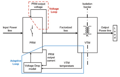
Fig. 2. Adaptive loop regulation conceptual diagram.
While the local voltage feedback loop maintains regulation at the PRM (regulator) output, the AL provides compensation for all the voltage drops that occur from the PRM output to the actual load (factorized bus line, VTM current multiplier and actual load supply line). The AL is based on a model that requires VTM temperature and factorized bus current as inputs. The predominant resistive behavior of power lines (factorized bus and output line) as well as the VTM, enables accurate modeling of the voltage drops. The accuracy of this model affects the regulation accuracy.
Analogy with power distribution, and improvements
AL is a new concept to the power electronic industry. The older method involved power distribution line drop regulators. Electromechanical voltage regulators are widely used in power distribution systems to maintain line voltage (at the service point or load) within predetermined limits and ensure the proper operation of lights, appliances, motors, and equipment. These regulators (an example is shown in Fig. 3) work on the same basic principle as AL. By measuring voltage and current locally, they estimate the line drop and compensate for it by increasing or decreasing their output voltage.
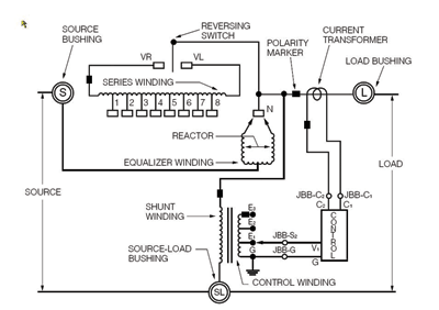
Fig. 3. McGraw-Edison VR32 regulator schematic.
One major difference, aside from the obvious dynamic performance of several kHz vs. few Hz, is the temperature compensation. Thanks to the Positive Temperature Coefficient sensor in the VTM, AL is capable of accurately tracking and compensating for the drop parameters affected by temperature, specifically the VTM current multiplier. This is important, as electronic systems require higher accuracy and are subject to wider temperature excursions than power distribution systems.
Control: side by side comparison with traditional isolated feedback
Dc (steady-state) design: zeroing the error
Standard regulation techniques like remote sense closed loop [3] are based on direct observation and integral error compensation of POL voltage. The steady-state voltage error (compared to the reference) is therefore forced to be zero. Reference voltage and sense technique accuracy are the main terms (factors?) that determine the overall accuracy of POL voltage.
In the case of AL, the same observations are valid for the PRM regulator. Local loop voltage reference and sense divider contribute most to the accuracy of the PRM output voltage. Any drop on the distribution lines and the VTM current multiplier is compensated through a pre-calculated model, which is affected by parametric spread of both impedance (device to device) variation and temperature dependency. The best modeled AL compensation scheme will compound the two accuracies and perform accordingly.
The resistive (linear) nature of the VTM current multiplier and its tight variation over temperature and population allows AL to achieve accuracy distribution similar to traditional closed loop control schemes. Fig. 4 shows the obtained voltage accuracy for a statistically significant population of 48-V input, 1.2-V output, 200-W AL based power systems over line, load, and temperature.
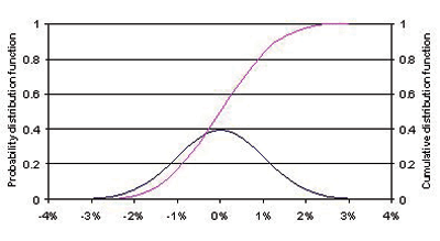
Fig. 4. 48-Vin, 1.2-Vout, 200-W AL-based power system regulation accuracy distribution; 1% tolerance resistors used on compensation.
Ac (dynamic performance) design: what affects the control loop
The VTM current multiplier exhibits an ac (frequency domain) characteristic of a broadband transformer, i.e. constant gain (K factor) up to 500 kHz and above, depending on the model. This is particularly appealing in the frequency domain, as current multiplication is provided without impact to the regulator compensation and dynamic performance. Moreover, any capacitance on the output of the VTM will be effectively reflected to the input reduced by a factor of K2, minimizing the impact on the bandwidth achievable by the PRM regulator.
In summary, the broadband current multiplier (VTM) enables local regulator loop effectiveness for ac purposes and the predictability of drops (through modeling) for dc purposes.
System thinking
To understand the advantages and disadvantages of AL as compared to classic switching mode power supply designs from a system integration perspective, see Fig. 5 which provides a generic application schematic for a forward converter. This is a common, discrete approach to a single output, isolated dc/dc converter in the 100 to 300-W power range, viable for comparison with the Factorized Power schematic with AL in Fig. 2.
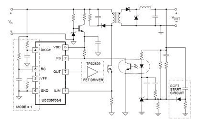
Fig. 5. Forward converter application diagram example
The following considerations illustrate the main differences in the power system designed in the mainframe system.
Isolation barriers and safety
In conventional designs, both the power stage (primary to secondary) and the feedback need to be isolated. While the industry has become accustomed to this requirement and its trade-offs and costs, it is advantageous in terms of system reliability (MTBF) to:
• Eliminate the number of isolation devices from a current multiplier and an optical device to just a current multiplier.
• Eliminate the isolation device which is more prone to aging. Optical components change their characteristics with time, while magnetic devices do not.
• Improve overall isolation safety. Optical device packaging can pose isolation issues if not properly protected from environmental conditions or if packaging degrades over time.
Total components count and reliability
There is another important reason to favor an integrated solution versus a discrete design. Each time that a power system is co-designed with the powered (host) system, secondary SELV circuitry erodes “precious” PCB space from the actual application. In other words, high value portions of the system, including high speed communication signal processing devices and memory, need to merge with low value components, often on more expensive and complex PCBs with a higher number of layers.
Accuracy
Fig. 4 shows voltage regulation accuracy with AL, with standard 1% tolerance components and the provided voltage reference. When the application requires tighter voltage control, it is possible to improve the accuracy distribution with few external components, all PRM referenced. All of the AL benefits in the system will therefore be maintained.
The easier way to achieve higher accuracy is to
• Connect an external, high precision voltage reference to the SC pin (0.2% tolerance or better) and
• Use 0.1% tolerance resistors for the AL compensation.
These changes will tighten the distribution by more than 1% on each end, bringing the three standard deviation values below 2%.
Design cycles
The AL technique thrives on dc and ac VTM performance. This directly impacts the power system design time, reducing time to market for the end use system. With dc, the VTM resistive behavior enables easy modeling of the distribution drops. Simple estimates of trace resistance and available data on VTM characteristics allow engineers to quickly design AL components.
With ac, the high bandwidth of the VTM enables the PRM regulator’s full dynamic performance to be transferred to the PoL efficiently. Moreover, the load characteristic is also transferred to the regulator with a gain of K2, where K is the turn ratio. This greatly minimizes the impact on ac performance for a wide range of load characteristics. Factory-optimized PRM regulators can be dropped-in without the hurdle of optimizing an external feedback system, therefore completely eliminating a significant design step.
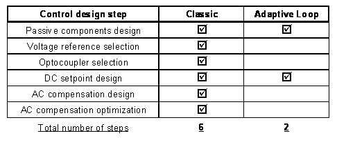
Table 1. Design steps comparison, classic closed loop feedback vs. Adaptive Loop
Adaptive Loop is a state-of-the-art regulation technique ideally suited to embedded power system designs. Significant advantages can be achieved in terms of performance, power density and efficiency. The technique reduces development cycle and costs and potentially speeds time to market. ■
Advertisement
Learn more about Vicor


