ICs with on-board oscillators requiring low-frequency fundamental crystals are commonplace, but now IC frequency multipliers require the higher frequencies of third overtone crystals. Compared to its fundamental implementation however, the third-overtone (3OT) crystal oscillator is more complex, with different crystal characteristics plus additional reactive elements and higher gain.
3OT
Most crystals use the fundamental thickness-shear vibration mode of AT-cut quartz. The practical upper limit of fundamental operation is around 50 MHz because the fundamental resonant frequency is inversely proportional to thickness. Frequencies higher than 50 MHz become too thin to handle during the manufacturing process. While a few crystal manufacturers can make fundamental crystals to 600 MHz or more using the inverted mesa process, 3OT manufacturers are more prevalent.
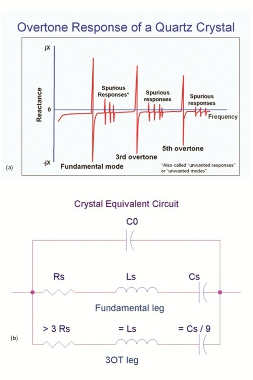
The 3OT is a crystal mode that resonates at three times its fundamental frequency. There are in fact an infinite number of odd harmonics that exist on the same quartz plate. The first, third and fifth harmonics are shown in Figure 1a with some anharmonic modes or spurs shown in between. Spurs are by-products of other vibrational modes and a good crystal manufacturer makes sure that these are minimized.
The AT-cut crystal has the equivalent circuit (see Fig. 1b) of a series RLC for the fundamental and each harmonic mode plus a capacitor, C0 , in parallel due to the electrodes. The 3OT series resistance, Rs, is more than three times that of the fundamental mode. Its series capacitance, Cs , is nine times less. This lower Cs in the 3OT will make tuning or calibration harder in the oscillator. If the crystal is too far off nominal frequency, there is less chance to electrically correct this in the oscillator. The 3OT has higher Q, which is the most important feature next to its higher frequency, as it results in better jitter and phase noise. Because the 3OT plate is as thick as a fundamental one-third its frequency, it is structurally robust with very good aging characteristics.

Fig. 1: The first, third, and fifth harmonics are shown in (a) with some anharmonic modes or spurs shown in-between.The AT-cut crystal has the equivalent circuit, shown in (b), of a series RLC for the fundamental and each harmonic mode plus a capacitor, C0 , in parallel due to the electrodes.
A 3OT oscillator design is more complicated. In general a crystal oscillator will always run on the fundamental, as it is the lowest resistance mode. While the 3OT has the next lowest mode in resistance, to operate on it, the fundamental must be suppressed. In Fig. 2 the top circuit is a fundamental Pierce crystal oscillator, a stable and common configuration for IC oscillators. It consists of an inverting linear amplifier and two 'PI' capacitors, C1 and C2 , on either side of the crystal. The resistor shown can standalone or represent the output resistance of the inverter. The crystal is calibrated to operate with a capacitive load so it looks slightly inductive and therefore resonates with the two PI caps – which from an AC point of view are in series. Around the loop there is 360° of phase shift to meet one of Barkhausen's criteria. The inverter contributes a little more than 180° phase lag, the R-C accounts for a little less than 90°, and the crystal (operating inductively) with the second PI cap, contributes a little more than 90°. With enough gain to overcome the crystal resistance, and feedback elements, it meets the second of Barkhausen's criterion and it will oscillate.

Fig. 2: In (a) the Pierce crystal oscillator is considered a stable and common configuration for IC oscillators. In (b) is a 3OT oscillator with a fundamental rejection circuit.
The bottom circuit of Fig. 2 is a 3OT oscillator with a fundamental rejection circuit. An LC tank replaces the first PI capacitor in the fundamental oscillator. The tank is designed to be capacitive at the 3OT frequency and inductive at the lower fundamental frequency. In this way, the fundamental mode will not run because the phase shifts around the loop will not add up to be 360°, but the phase conditions for the 3OT will be correct when the tank is capacitive. Oscillation will occur provided that there is sufficient gain to overcome the increased resistance of the 3OT crystal.
Another option is to put a high-pass filter in with the amplifier, starving the gain at the fundamental but allowing sufficient gain at the 3OT frequency. In this way an LC selector network is unnecessary though it may take more than one IC with different high pass filters to cover wide frequency ranges. The PI caps are built into the IC so only the crystal is required externally. 3OT IC oscillators also integrate inductors for the tanks to select the 3OT or create high pass filters to reject the fundamental.
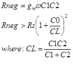
Increased gain, commonly referred to as negative-R, is required for the 3OT because of the higher resistance. Negative-R however is not flat across a frequency range. The IC manufacturer must not only guarantee that there is enough gain at the desired frequency, but there must be enough gain with C0 across its terminals. Too little gain may cause starting problems. The required gain can be calculated with the following formula.

gm is the transconductance of the gain element
ω is the angular frequency of interest
C1 and C2 are the PI capacitance values
C0 is the electrode capacitance of the crystal
Rs is the series resistance of the crystal
Rneg is the loop gain
CL is the load capacitance around the crystal
There are slight but critical differences in making the 3OT crystal. The frequency vs temperature characteristics are different for the same angle cut. While they are both AT-cut crystals, which are cut nominally at 35°12’ from the Z-axis, the angle for the 3OT needs to be approximately 8’ more to have equivalent temperature performance. Polishing is required for the best Q and flatness must be monitored for spur reduction. The quality of the quartz can also make a difference. Q’s of 1.8 million or greater are recommended although Q’s as low as 1 million are quite common.
Packaging
The crystal package size is also a factor. Miniature resonators are more susceptible to mount stresses and thermal mismatches in the packaging. The thickness-shear vibration of the quartz is mostly confined between the electrodes, but the wave gradually dies off outside the electrode area before it reaches the edge and reflects back. The smaller the package, the more the electrode has to shrink to keep the distance from the edge, but this raises resistance even more. With rectangular blanks the length and especially the width of the plate play a key role in proper mode activity. As the package shrinks, resistance, Q, coupled modes, and drive level effects become challenges as well.
The 3OT crystal with the IC oscillator has emerged. Higher communication speeds that require higher frequencies, lower jitter and lower phase noise demand a 3OT oscillator. The semiconductor state-of-the-art has the amplifier gain, bandwidth, and component integration capabilities to use the 3OT crystal. It is not as simple as the fundamental crystal oscillator, but proper consideration of the differences in the 3OT crystal and the IC oscillator design should make the combination a success.
Advertisement
Learn more about Connor-Winfield


