By PRAVEEN POTHAPRAGADA
President
Equipto Electronics
www.equiptoelec.com
In parts of the world where weather conditions are within a temperate range, electronics has embedded itself into many different types of infrastructures. In fact, there is hardly any place left on earth that does not have intelligent electronic systems performing control and monitoring functions. There are, however, places on the planet where high temperature, sand, and other conditions can be challenging to overcome. As electronic circuitry is by nature fragile and temperature sensitive, packaging electronics to be functional in harsh environments is evolving into a special science. In recent years, infrastructure growth has exploded in locations previously stuck in a perpetual low-tech time warp. Some of the middle-eastern countries are prime examples.
Traditionally, NEMA-rated enclosures have been popular choices for protecting systems in harsh environments. However, simply packaging circuitry in a NEMA-rated enclosure is not enough to ensure adequate protection from an environment with blistering daylight temperatures and the incursion of contaminants. While thermal management may not be top-of-mind for most EEs, it is vital for the longevity of systems in harsh environments. The required thermal analysis does not need be a daunting ordeal for every system. “Back of the envelope” style calculations are sufficient most of the time in determining the airflow required to keep the system functional.
In a very warm climate
Consider the project to greatly expand the Dubai International Airport and boost its capacity by 50% to 90 million passengers per year by 2018. To accomplish this, it was necessary to build a people-mover system to transport passengers between Terminal 1 and the new Concourse 4. The INNOVIA APM 300 automated people-mover (APM) system (Fig. 1 ) was selected by the airport. Built by Bombardier Transportation, an international rail transportation leader, it will move passengers at speeds up to 80 km/h.

Fig. 1: The INNOVIA APM 300 automated people-mover (APM) system by Bombardier Transportation will moves passengers at speeds up to 80 km/h at Dubai International Airport.
Modern people-mover systems are fully automated, with no on-board system personnel. As such, various control and monitoring systems must be located throughout the rail line. Unlike at most airports, ambient daytime summer temperatures of 118°F (47.89°C) are not uncommon in Dubai, with nighttime drops of 20°F or more. Sandstorms also occur periodically. These APM systems are, of course, fully exposed to Dubai’s harsh environment.
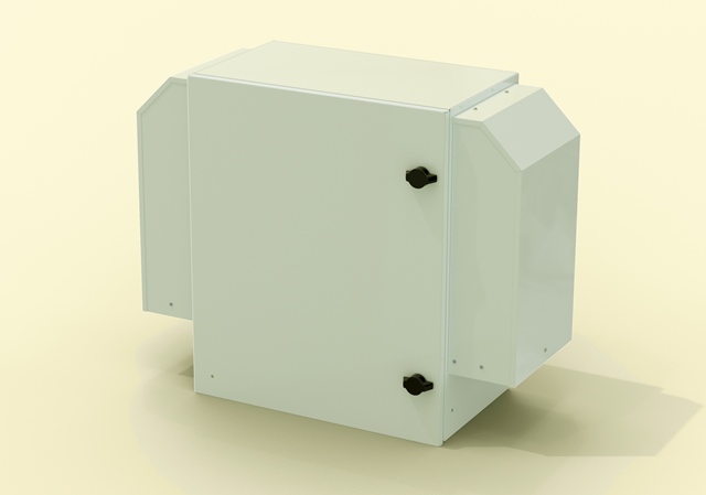
Fig. 2: Equipto NEMA 3R enclosures were chosen to protect system control circuitry for the INNOIVIA APM 300.
For some of the system control circuitry, NEMA 3R enclosures were chosen for the task (Fig .2 ). In planning for circuit protection, the challenge was to determine the airflow needed in the enclosure to keep the system operational and not shorten the lifespan of any of the components. Here, the given factors that were at play are shown in Table 1 .
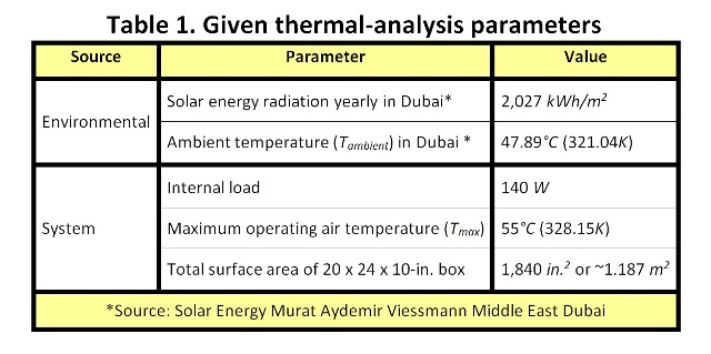
At any time, only half the surface area of the enclosure, at maximum, is directly exposed to the sun. So the heat energy due to the sun, or solar load, can be calculated thus:
Solar load=[yearly radiation (Wh/m2 )/(days/year×hours/day)] × enclosure surface area(m2 )/2
=[2,027,000/(365×24)] × 1.187/2
=137 W
The total load, or heat energy (Q ), that must be dealt with by air circulation is the sum of the solar and internal loads: 227 W (or J/s ). The airflow (CFM) that is needed to deal with Q can be calculated using the following two equations:
(1) Q= m× cρ (∆T )
where m is the mass of air per second (kg/s ); cρ is the specific heat of air at 325K (1006 kJ/kgK ); and ΔT is the difference between internal and external air temperature, or Tmax (328.15K) minus Tambient (321.04K).
And
(2) m =CFM ×ρ
where CFM is the rate of air flow (here in m3 /s ) and ρ is the density of air at 325K (1.109 kg/m3 ).
Substituting for m in the (1), and solving for CFM :
CFM = Q/[cρ ρ(∆T) ]
= 277/[1006×1.109×(328.15 – 321.04) ]
= 0.035 m3 /s or 74 ft3 /min
So if we use a 100-ft3 /min fan to establish the airflow in the enclosure, the system should remain operational within its engineered environmental range and not overheat.
Note, however, that a detailed analysis is still required for critical systems to determine if any hot pockets exist and if there is airflow reduction from any required filters. But a simple analysis such as the one above can give us a starting point in designing such enclosure systems.
Other conditions
Other environmental conditions may require specialized enclosure finishing, gaskets, and air filters. Blowing sand and microfine dust, often achieving significant velocity, can be another challenge in the Mideast, and even the western U.S. While exact recommendations will vary with the type of environment, a safe bet is to choose an enclosure fabricated from a noncorrosive metal, such as stainless steel or aluminum. Paint and plating finishes can also protect the base metal, but sometimes get scratched or degraded upon years of exposure. Again, this depends on the environment and how the enclosure is used and even how it is positioned. For painted finishes, the surface should be fully primed before applying the final finish. A good epoxy paint finish will have a thickness of 2 to 4 mils.
The gasket seal can be especially important in wet or dusty regions. Choose one that corresponds to the ratings of the harsh environment your product will interact with. Many different types of gaskets are available in the market, ranging from dust gaskets to water- and jet-fuel-tolerant ones. For salt water tolerance, look for MIL-STD 810 compliance.
To ensure that the enclosure retains its structural integrity, it should be seam welded and tested for weld discontinuities (die penetration test). Your enclosure manufacturer should be able to supply you with this data. If the enclosure is being custom made to your specifications, be sure to supply the manufacturer with all possible data about the installation, what circuitry will be mounted inside the box, and the environmental conditions expected.
Mechanical vibration can also be a significant issue if the enclosure will be mounted in a mobile or shipboard installation. For these situations, look for certification that the enclosure meets MIL-STD-167-1 (Mechanical vibrations of shipboard equipment) and MIL-STD-901D (Shock, Heavy Weight Grade A, Class II). This is especially important if the mobile application is off-road.
Advertisement
Learn more about Equipto Electronics


