BY MARIO DIPIETRO
Product Marketing Manager, Flatpack Division
Cornell Dubilier Electronics, Inc.
www.cde.com
The ever-increasing trend toward miniaturization and flatness of electronic devices is a given for consumer markets, but now the demand for smaller power circuits has also spilled into industrial and military applications, in which space and weight savings are requirements for next-generation designs. The challenge for system design engineers is to source smaller components to save space without compromising system life and reliability.
This is especially difficult when sourcing for capacitors, which are often among the tallest components on a power-supply board. The alternative is to spread the capacitors over large areas of PC board when banked in parallel to meet minimum capacitance requirements for hold-up and bulk storage. However, capacitor manufacturing technology and techniques are improving, leading to the reinvention of the humble aluminum electrolytic capacitor to achieve flatter package styles to help power-supply designers meet their design needs.
Electrolytic capacitor’s evolution
Over the past decade, capacitors have seen incremental technology improvements that have helped to shrink component size. As an example, improvements in material specifications such as high-gain anode foils for aluminum electrolytics have helped achieve higher CV (capacitance * voltage) ratings for a given capacitor size. The development and application of new electrolyte systems and improved lead attachment technology have helped to lower ESR, thereby reducing power loss for the same amount of ripple current and allowing for smaller components to be used without overheating. Typically, these advances have been applied to existing package styles (form factors), which have limited potential space savings.
Cylindrical packaging has been the dominant form factor for aluminum electrolytic capacitors since their invention. While this design concept has facilitated efficient manufacturing, it has created challenges for component designers seeking to achieve significant size reductions along with substantial gains in operating life. In addition, electrolytics have historically suffered from dry-out over time, thereby limiting their lifespan.
Before discussing the role that other package types can play in improving energy density and life expectancy, it is useful to look at how conventional aluminum electrolytic capacitors are constructed. Two layers of specially etched aluminized foils are separated by insulating layers of paper (impregnated with a liquid electrolyte), wound together to form a cylinder, and packaged in an aluminum housing. One foil has an oxide layer, which becomes the anode; the second is the cathode. The cathode and anode are connected to leads or terminals, and the housing is sealed with a rubber gasket to prevent the electrolyte from escaping. The housing also has a vent, intended to relieve internal pressure from hydrogen gas. The resulting package must be robust enough to withstand a wide range of operating conditions while keeping its electrolyte within the component. This packaging technology can eat up of a lot of space. In the smallest of SMT package sizes, the packaging materials (case, spacers, gaskets, etc.) can take up 60% of the total finished capacitor volume.
Competing technologies, especially tantalum capacitors, have achieved higher energy density and lower cost per CV compared with SMT aluminum electrolytics, especially at the lower voltages at which they dominate board-level applications for bulk storage and filtering. It is not uncommon to see arrays of tantalum capacitors on a PC board, connected in parallel to meet the hold-up requirements of the devices they serve. Tradeoffs between height reductions and board real estate must be considered because spacing between paralleled banked capacitors can further reduce the energy density of the total capacitance solution needed for bulk storage and filtering.
To meet the challenges of low-height profile, PC board footprint reduction, long life, and improved system reliability, Cornell Dubilier (CDE) has advanced its flat electrolytic capacitor technology to offer price and performance equal to or better than the more complex banked alternatives.
The company has been producing flat aluminum electrolytic capacitors (types MLP and MLS) for more than 20 years. Its Flatpack technology uses flattened capacitor windings to create high-energy-density designs with welded seals to prevent electrolyte loss over the course of the capacitor’s life — the Achilles’ heel of its cylindrical predecessor.
The welded seal eliminates the need for a gasket, which further improves energy density. Mostly used in military and aerospace applications, these prismatic types are extremely robust and have proven performance in the most critical applications for airborne power supplies and ship-board and ground-based radar systems. Over the past two decades, Flatpacks have made inroads in displacing wet tantalum capacitors, which had previously been the only high-capacitance types available with a hermetic seal and robust packaging. The availability of flat, robust, high-reliability capacitors has already helped military product designers shrink their board designs, save weight, and improve system reliability.
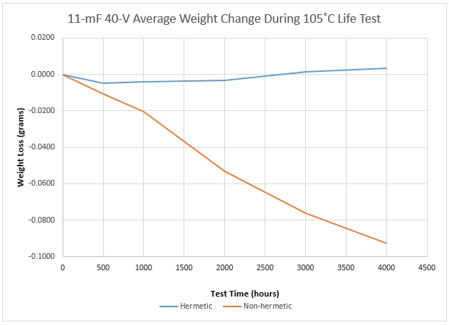
More recently, CDE has made several additional advancements in flat-capacitor design and packaging techniques that shrink the components even further. One critical example is improved seal technologies from “near hermetic” to “true hermetic” with glass-to-metal seals. The developments led to CDE introducing its MLSH Slimpack series of hermetically sealed aluminum electrolytic capacitors in 2016 (Fig. 1 ). Fig. 1: A comparison of electrolyte loss (by weight measure) from data taken during a 4,000-hour 105°C life test on the hermetic MLSH and non-hermetic capacitors.
These feature glass-to-metal seals that completely prevent dry-out of the capacitor electrolyte. As a result, specifications indicate that at rated voltage, operating life is 5,000 hours. Capacitance values reach 3,200 µF, with voltage ratings up to 250 Vdc. Packages are available as small as 1.0 x 0.5 x 1.5 in., with up to 80 g’s of vibration withstand.
The company’s upcoming THA series pushes energy density even further and is targeted for commercial and industrial applications as an alternative to arrays of tantalum or SMT aluminum electrolytic capacitors. Conceptually, it shares the flat internal design of earlier Flatpack types, but its aluminum enclosure is only 8 mm thin. The THA package is laser-welded to prevent electrolyte loss, offering a superior seal and extending service life and shelf life as compared to conventional package types. Rated for 85°C, the components have been tested to more than 5,000 hours at rated conditions. CDE plans to offer a 105°C version, type THAS, wrapped in a steel sleeve to provide even greater rigidity.
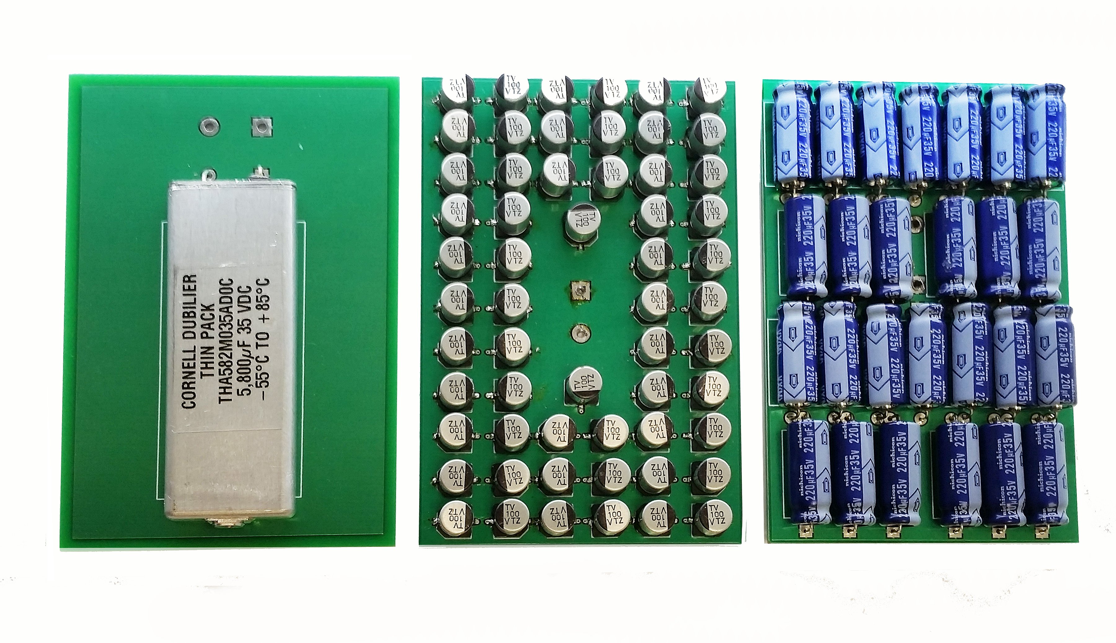
In general, a flat electrolytic can offer a significant improvement in profile (Fig. 2 ) and board-space reduction (Fig. 3 ) for an equivalent CV product to that of earlier technologies. Fig 2: Comparison of profile and footprint of THA (center) versus SMT aluminum electrolytic (left) and axial aluminum electrolytic capacitor bank (right) with similar values and ratings (35 Vdc at 85°C).
 Fig 3: The space-saving and component-count reduction potential of THA capacitors (left) versus an SMT aluminum electrolytic (center) and axial aluminum electrolytic bank (right) are substantial.
As shown, the space savings potential of the THA series component is substantial when directly compared with boards populated with banks of axial and SMT aluminum electrolytic capacitors for the same capacitance and voltage ratings (5,800 µF, 35 Vdc at 85°C). Note that on the boards containing the tantalum and SMT devices, there is also a lot of unavoidable space between capacitors.
In addition to the compactness, tight seals, and robustness of the THA and MLSH components, use of a single component (versus multiple components) greatly simplifies assembly and significantly improves system reliability by reducing component count and connection points to the board. In the banked configurations, the failure of just one capacitor could prevent the entire bank from functioning.
As future applications demand thinner storage applications, we will continue to see a corresponding reduction in capacitor profiles. Cylindrical capacitors will continue to dominate where fully optimized space and weight requirements are not required. Even within the flat package design, there is room for continued improvement.
Advertisement
Learn more about Cornell Dubilier


