Selecting the best part for today’s portables depends on
its electrical and mechanical properties
BY KENG CHEN and KIMMO KOSKINIEMI
Pulse Antenna Division
San Diego, CA
http://www.pulseeng.com
The antenna plays a major role in the reliability and performance of any wireless communication system. Selecting the antenna that best meets the system’s criteria is critical.
However, today’s small handheld devices also challenge antenna designers with demands for ultrathin, compact sizes and high-performance that has the ability to meet multiple standards. Time to market and cost are two other important criteria for device manufacturers to consider.
Two major criteria in selecting the best antenna for your system are the electrical and mechanical properties of the antenna. Some of these are constrained by the design and mechanics of the device.
Basic electrical properties
The basic electrical properties that should be considered are operating frequency, bandwidth, maximum gain, average gain, efficiency, return loss or voltage standing wave ratio (VSWR), polarization, directivity, side- and back-lobe levels, front-to-back ratio, radiating patterns, impedance, and power rating. The materials selected and the actual radiator RF design also determine the antenna’s final electrical performance. The materials used need to have low loss (tan ∂) and good conductivity.
Operating frequency
Operating frequency is determined by the type of application. For example, Wi-Fi 802.11 b/g, ZigBee, and Bluetooth use the same 2.4-GHz ISM band that has a bandwidth of about 80 MHz (2.4 to 2.48 GHz). A commercial GPS system uses the L1 1.575-GHz band with a bandwidth of 2 MHz (1,575.42 MHz ±1 MHz).

An internal, multihybrid, cellular penta-band antenna is typically used for worldwide roaming and interoperability.
A GSM system uses the 850/1,900-MHz band or the 900/1,800-MHz band, depending on the region of the world. 3G systems use a variety of bands, depending on region. For example, the European WCDMA system uses the 2.1-GHz band.
Quad- or penta-band cellular band antennas are often used for worldwide roaming and interoperability as they combine 4-band GSM and W-CDMA 2100 to receive and transmit signals in all cellular bands. Other applications include WiMax, UWB, ISM900, ISM5/5.8GHz, DVB-H, MediaFLO, DECT, RFID, VHF, UHF, AM, and FM.
Multiantenna systems, such as diversity and Multi In Multi Out (MIMO), are used in applications where enhanced data rates are needed. With multiple antennas, it is crucial to design and characterize the whole antenna system including antenna-to-antenna isolation and correlation coefficient testing.
Gain and efficiency
The maximum gain, average gain, and efficiency determine the range and performance of the antenna. The higher these numbers, the better the range and performance of the antenna. Also, the antenna should have sufficient VSWR in the operating frequency range.
Typically, a 10-dB return loss (2.0:1.0 VSWR) or better is a respectable number. Consider the maximum gain with efficiency or average gain in order to get a better picture of the overall performance of the antenna. Be careful not to fall into the trap of looking at just one of these properties and jumping to a conclusion.
Maximum or peak gain is a good gauge in evaluating directive antennas, but can be a misleading term if used as the primary criteria to determine general antenna performance. Often, in more complex devices, the gain is lower so there is implementation loss when the antenna is placed and connected to the actual device.
This is because high peak gain always means some level of directivity and may result in antenna gain that is much lower in some other direction due to nulls in the radiation pattern. Selecting an antenna that has a margin over the recommended decibels ensures that it will meet system requirements in the real world.
Most wireless systems have 50-Ω impedance, which the antenna should match as closely as possible for minimum mismatch/loss in the system. Other factors to consider are polarization (vertical, horizontal, or circular) and the radiating patterns (in xz, zy, and xy planes) in order to fully characterize the antenna.
Most handheld portable devices need a linearly polarized antenna with omnidirectional radiating patterns for 360 omnidirectional coverage. True omnidirectional radiating patterns exist only in theory.
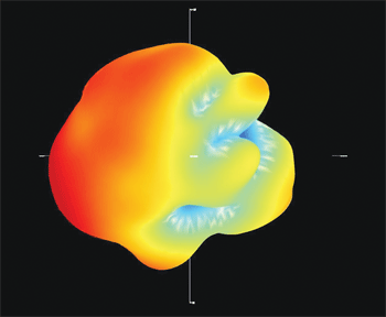
Often, device mechanics affect antenna patterns, causing nulls and directivity in the patterns. In many cases, the best way to determine true antenna performance is the total 3-D radiated efficiency of the antenna, as it indicates how much of the antenna’s energy can be transferred to radio waves and how much is lost due to mismatch and radiation losses.
Especially in small portable or handheld devices, 3-D efficiency is a much better parameter to compare than maximum gain because in actual use the device can be in any orientation. In addition, because in use the maximum gain peak beam can be directed toward the user’s body, the gain is lost due to body attenuation.
Mechanical layout
The mechanical layout of the device’s design determines the size and type of antenna needed, and the size and type of antenna needed also limits and determines the antenna’s electrical properties. Therefore the mechanical design of the device should be considered hand in hand with the selection of the antenna.
Typical mechanical properties are form factor (external or internal), construction, size, mounting, type of connection, and aesthetic considerations, along with the mechanical durability and reliability of the antenna component. Material selection and mechanical design of both the device and the antenna have direct impact on manufacturability.
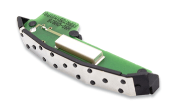
Competent selection leads to cost-effective easy-to-manufacture solutions, especially for very high product volumes. Significantly, a bigger antenna does not necessarily correlate with better antenna performance. This is demonstrated by small, ceramic-chip antennas that can outperform much larger antennas when implemented following design guidelines.
Internal antennas
Most handheld devices will need an internal antenna, instead of an external one, for purely aesthetic reasons. In fact, more than one antenna will be needed depending on the applications and functions of the device.
The typical construction of the internal antennas are stamped metal, PCB, flexible printed circuit (FPC) on plastic carrier, meander line, LTCC, ceramic, quadrifilar, and patch antenna. The size and mechanical constraints of the device, as well as the electrical requirements, also determine the type of construction/technology to use.

One way to determine true antenna performance is to look at its total 3D radiated efficiency.
Most of these internal antennas can be mounted through a SMD process, SMT process, pogo pins, spring contact, mini U.FL/I-Pex connector or direct solder. When long-feed cables are used, it is important to factor in signal loss from the cable, which can be several decibels.
The ability to solve some of the most demanding design issues in small, handheld devices with multiple radio applications will narrow the antenna selection and the type of technology needed. Some of these challenges are isolation, minimum gain and efficiency, hand/body effect and specific absorption rate.
Isolation becomes an issue when multiple antennas are located close together in a small handheld device. Antennas that operate in the same or in a close frequency range couple among themselves and cause a reduction in performance.
The minimum gain and efficiency requirement becomes a challenge in small devices due to proximity to other components such as the LCD, metal shields, battery and other electronic components. The lower-frequency applications, such as 850- and 900-MHz bands, are challenging due to the longer wavelength in the lower operating frequencies.
Hand/body effect requirements become an issue in a handheld device due to frequency detuning when the device is held close to human body tissue. The resonance frequency will be shifted out of band and cause a high attenuation in the signal due to impedance mismatch and degradation in antenna performance.
Also, the tissue near it absorbs the radiated energy from the antenna and prevents the signal from propagating to the open air. Likewise, SAR requirements should be considered due to regulatory requirements.
Due to the high isolation property and distributed nearfield radiation of these special ceramic antennas, SAR and body/hand effect can be reduced to a minimum and excellent isolation can be accomplished even in a small, handheld device.
Ceramic antennas
We also need to be careful when choosing a ceramic antenna. While there are many different types of ceramics, LTCCs, and ceramic monopole, performance varies and results might differ when compared to the proprietary ceramic designs of individual antenna companies.
Consistency of design and performance specifications is critical, so it is beneficial to work with an antenna company that has strong intellectual property, research, and engineering capabilities. Even with miniature ceramic antennas, a 70% to 80% efficiency, 1 to 2-dBi max gain, and better than 3-dBi average gain can be achieved if the right antenna is selected and proper design guideline is implemented.
All antenna products should be fully field tested to ensure quality and reliability. These tests include mechanical and reliability testing, such as mechanical and temperature shock, vibration and extreme temperature testing, as well as testing the pre-designed mechanical interface prior to assembly. Electrical characterization should be performed with plastic covers, a phone shell, and a phantom head/hand, as though a person were actually using it. ■
For more on antennas, visit http://electronicproducts-com-develop.go-vip.net/controls.asp
Advertisement
Learn more about Pulse Engineering


