By TOM HOPPIN,
Application Specialist, RF and Microwave Handheld Analyzers,
Keysight Technologies
www.keysight.com
Mission-critical radar systems are a rapidly growing part of the aerospace and defense industry. Often classified as ground-based, airborne, ship-based, or space borne, they are used in a wide range of applications spanning traffic enforcement, meteorology and weather prediction to military air defense. Once installed, they must be routinely maintained to ensure their optimal operation in the field. Occasionally, troubleshooting and repair may also be necessary.
To assure the highest uptime, that troubleshooting and repair must be done quickly, accurately and often times, in any weather condition. That’s a hefty task considering the complexity of modern mission-critical radar systems, the challenging and sometimes dangerous environments in which they are located, and the decades-old benchtop equipment engineers must typically use to measure them. Fortunately, breakthrough technologies available in modern “all-in-one” or combination analyzers are now transforming the way maintainers validate the performance of mission-critical radar systems in the field.
Just the basics
For the purposes of this article, commercial Air Traffic Control (ATC) radar will be used as an example. ATC radar systems are classified as either primary or secondary. Primary radar transmits high-frequency waveforms or signals toward a target. The transmitted pulses are reflected by the target’s surface and received by the same radar. The reflected energy (echo) is then measured at the radar’s receiver to extract target information. A prime example of primary radar is unmodulated Continuous Wave (CW) radar, which can measure target velocity and angular position. Range information is typically extracted using some form of modulation such as a pulsed waveform.
Secondary or beacon radar overcome the limitations of primary radar by creating a two-way data link between a ground station and an aircraft. Modern beacon systems like the Air Traffic Control Radar Beacon System (ATCRBS) separate the interrogation and reply frequencies, which results in stronger received signal levels at the ground station and improved weather-related performance.
When installing, maintaining and troubleshooting primary and secondary radar systems and components in the field, engineers must generally measure both their time- and frequency-domain performance over a variety of test conditions. They may also have to field test and tune the numerous functional blocks or Line Replaceable Units (LRUs) that make up the radar. This task is especially difficult in monopulse radar systems, which are commonly used to derive the angular information of a target. Because of the unique amplitude and phase relationships between the various channels in a monopulse system, testing LRUs often requires coordinating and comparing waveforms in the time and frequency domains.
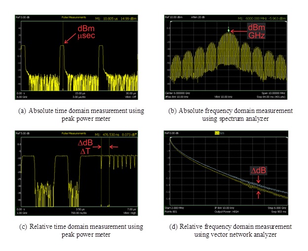
When field testing the operation of a radar system’s LRUs, a set of basic time and frequency measurements are performed that result in absolute and relative measurements (Fig. 1 ). Relative time-domain measurements show the relative measurements between two points in time, and are particularly useful for characterizing timing features (e.g., pulse width, rise time, fall time, and pulse repetition interval). For monopulse radar systems, another important measurement is the relative phase between multiple channels.

Fig. 1: Shown here are time- and frequency-domain measurements of radar signals captured using a single FieldFox combination analyzer from Keysight Technologies. For both absolute and relative measurements, a marker can be used to measure the peak amplitude at a specific point in time or frequency within the signal pulse.
Instrumentation choices for field testing
Successfully making all of the time- and frequency-domain measurements needed to precisely validate radar system and LRU performance in the field requires the engineer to select the appropriate instrumentation and test approach. That leaves the engineer with two basic options, either to adopt a traditional approach that involves using 3-4 different benchtop instruments—each measuring a specific function (e.g., power, spectrum or frequency response)—or use a modern all-in-one or combination handheld analyzer.
With the traditional approach, absolute frequency-domain measurements may be made using a variety of instruments, such as a spectrum analyzer, vector network analyzer (VNA) or vector voltmeter (VVM). LRUs containing their own signal source are measured using a spectrum analyzer. VNAs and VVMs can be used to measure the amplitude and phase of transmission paths that include cables, filters and amplifiers. Relative time-domain measurements, on the other hand, are made using a peak power sensor and peak power meter, while relative frequency-domain measurements are performed using a spectrum analyzer, VNA and VVM.
The traditional approach, while effective, has a number of drawbacks; not the least of which is the hassle of having to carry multiple instruments into the field and ensure the test site has adequate weather protection to guarantee the safety of the equipment against harsh weather conditions. Benchtop instruments also typically require a warm-up time as specified by each individual instrument’s manufacturer.
Above and beyond these challenges is the fact that benchtop instrument accuracy is usually only specified by the manufacturer when operated at a set temperature (e.g., 23 +/- 5 degrees C). In the field, testing may occur over a wide range of environmental conditions and this can lead to uncertainty in the measured data. Further complicating matters, older benchtop equipment is often used for field testing, much of which is well beyond its service life and therefore, unrepairable by the manufacturer.
The obsolete equipment can be replaced with newer options; however, a one for one instrument replacement is not optimum. Doing so would reduce the overall cost-of-test since newer instruments typically have 3-year warranties and lower overall calibration and repair costs. Newer instruments also typically have higher performance, improved accuracy and functions specifically designed for field testing.
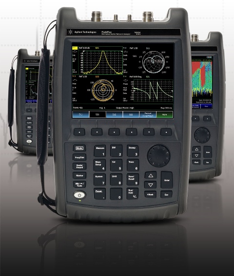
The other, much more cost-effective option for field testing radar systems and LRUs is to replace the multiple benchtop instruments with a single combination handheld analyzer (Fig. 2 ). Such instruments not only offer performance comparable to that of benchtop instruments and functionality geared toward field operation, they also encapsulate the capability of multiple instruments into one ruggedized piece of equipment (Fig. 3 ). That means only one instrument needs to be carried into the field, and it requires no special protection from adverse weather conditions. Moreover, modern combination analyzers generally have the ability to make accurate measurements at startup, rather than requiring a lengthy warm up, and can automatically correct the measurements for temperature changes over a specified range.

Fig. 2: Keysight’s FieldFox is an example of a combination analyzer well suited to radar system and LRU measurements in the field. Specifically designed with the durability needed for field testing (US MIL-PRF-28800F Class 2 standard compliance), it includes a peak power meter, spectrum analyzer, VNA, and VVM all in a six pound instrument. FieldFox’s InstAlign feature allows the spectrum analyzer mode to make accurate measurements immediately at turn on and also automatically corrects measurements for any temperature changes over a range of -10°C to +55°C.

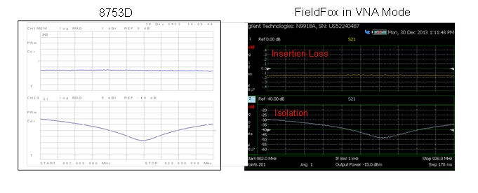
Fig 3. Time- and frequency-domain measurements made using the FieldFox combination analyzers have been shown to correlate, often to within hundredths of a dB, with benchmark data taken in the development lab using benchtop instruments, and at system installation. Shown here is a comparison of the measured frequency response of an RF duplexer based on a ferrite circulator using an 8753D benchtop VNA on the left and FieldFox operating in network analyzer mode on the right. The two instruments produce almost identical results.
The key benefit to using a combination analyzer for field testing radar systems rather than the traditional multi-instrument approach is a reduction in the overall capital and operating expenditure. A single combination analyzer can replace all four RF instruments traditionally used for civilian radar test. Moreover, it is less expensive than comparable benchtop instruments and often has a lower annual calibration cost. Finally, because engineers need to only use one combination analyzer versus multiple other instruments, the combination analyzers minimize training time and costs.
The combination analyzer in action
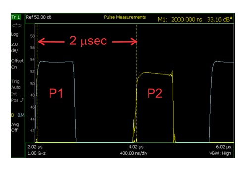
To better understand the benefits of using a combination handheld analyzer for field testing radar systems, consider the measurement of pulse timing in commercial ATC radar with sidelobe suppression (SLS). SLS is a technique whereby a secondary channel is added to a monopulse radar system to improve its performance. ATC radar communicates with SLS using two separate transmitters. One transmitter is connected to a high gain antenna, while the other is connected to an omnidirectional antenna. The SLS control pulse is transmitted through the omnidirectional antenna as the single P2 pulse. There is a 2 microsecond delay between the P1 and P2 pulses.
In this case, measuring the relative timing requires two separate peak power measurements and can easily be performed using a combination handheld analyzer like FieldFox with a U2020 X-series power sensor. The measurement begins with the power sensor connected to the primary transmitter generating the P1 pulse. The power sensor is triggered using a TTL control signal delivered from the radar system. The P1 measurement is stored in the analyzer’s memory. Next, the power sensor is moved to the auxiliary transmitter for the P2 measurement. The same TTL signal is required to properly trigger the power sensor for this second measurement. Finally, markers are used to measure the timing offset between the P1 pulse (stored in memory) and the P2 active measurement. The actual measurement of the relative timing offset between P1 and P2 is shown in Fig. 4 .

Fig. 4: This measurement of the ATCRBS transmitter P1/P2 timing offset was captured by Keysight’s FieldFox analyzer and the U2020 X-series power sensor.
In summation, properly installing modern mission-critical radar systems and ensuring their optimal performance requires routine maintenance, troubleshooting and occasional repair. While this challenging task can be accomplished via a traditional approach, using a combination handheld analyzer with multiple instrument capability provides a more convenient and economical solution. Using the combination analyzer, radar system performance can now be quickly and accurately tested in the field in any weather condition.
For more information on this topic, download Keysight’s application note, “Techniques for Precision Validation of Radar System Performance in the Field Using FieldFox Handheld Analyzers,” at www.keysight.com/find/fieldfoxapps.
About the author
Tom Hoppin is an application specialist in RF and microwave handheld analyzers with Keysight Technologies. He started his career as an electronic aviation technician in the U.S. Marine Corps. After his service in 1973, he joined Hewlett-Packard as a manufacturing technician. During his career at HP, he moved from manufacturing to production engineering and was promoted to engineer in 1989. Since then, he has held a number of engineering and management roles at HP and Agilent, focused on test system design and spectrum analysis. Tom retired in 2009 and has returned to Keysight as an application specialist for RF and microwave handheld analyzers.
Advertisement
Learn more about Keysight Technologies, Inc.


