ATCA/MicroTCA chassis systems for networking
The Telcom Computing Architecture provides a great basis for design
BY STUART JAMIESON
Emerson Network Power Embedded Computing
Edinburgh, Scotland
www.emersonnetworkpower.com/embeddedcomputing
Over the last 10 years the PICMG organization has been developing a family of specifications focused on supporting the packet based networking infrastructure. These specifications collectively have become known as the Telecom Computing Architecture or xTCA.
Developed first, Advanced Telecom Computing Architecture (ATCA) provides large (8U) blades that plug into a subrack and connects them to a protocol-agnostic, switched-serial backplane. ATCA provides full system management capability down to the module level, enabling hot-swap capability in every active system block, including electronics, fans and power supplies.
The Advanced Mezzanine Card (AdvancedMC or AMC) specification was developed as an extension to create modularity in ATCA designs. AMCs plug into ATCA blades to provide customization of I/O, hard drives, secondary processing, FPGA support, etc. Like ATCA blades, the AMC modules are hot-swappable units and can be individually monitored and controlled through the ATCA system management scheme.
During the development of the AMC spec, it was recognized that the AMCs could be used as the blade of a system. This led to the development of MicroTCA, which specifies systems created using AMC modules in a subrack, plugging them directly into a backplane. The result is a modular system, physically smaller and with a lower cost of entry to target low-cost infrastructure designs.

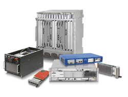
Fig. 1. ATCA, MicroTCA, and AMC solutions come in many different packages.
Right spec, right app
By examining application needs one can, at a high level, identify criteria that can help determine the appropriate xTCA type for a given application. For applications requiring significant processing or memory requirements, the large board size of ATCA provides a good match. But, if the processing and memory requirements can fit within a single AdvancedMC card then MicroTCA could be used.
Functional granularity and software flexibility is another area that can help define which specification to choose. If the functions within the application can be split among several boards, or fine-grained modularity is required, MicroTCA is a viable approach. Large, monolithic programs that must run on a single processor are more likely to need the capacity of an ATCA blade. With software that is readily split across several processors, the solution is less clear, as it can use either MicroTCA or ATCA.
Redundancy and availability must also be considered. Applications that require a significant amount of redundancy for high-availability operation may need the larger ATCA blades to avoid the need for multiple shelves.
For applications needing load sharing, it may be easier to implement with high-capacity ATCA boards, as they can handle the overhead to move system state information around and achieve the required performance levels. On the other hand, systems that use a fail-over approach may be easier to implement with the finer granularity of MicroTCA. The failure of a small board does not require as much of a hand-off as the failure of a large one.
There are physical and environmental considerations for both specifications. Both ATCA and MicroTCA.0 are focused on the NEBS central office environment. With installation space or power constraints, the compact nature of MicroTCA could make it a better fit. This is particularly relevant if the shelf depth is required to be 300 mm, as only MicroTCA can meet this requirement. In comparison, two-slot ATCA systems allow for more compact systems that also can fit within smaller space constraints (assuming depth is not an issue).
One area that is quite unclear is ruggedized environments. At the time of writing, ruggedized MicroTCA specifications are being developed by PICMG for both air-cooled and conduction-cooled environments. Not to be outdone, ATCA has also been applied to these ruggedized environments.
A wireless infrastructure app
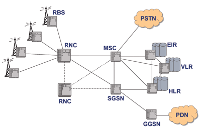
Consider the Universal Mobile Telecommunication System (UMTS) wireless infrastructure as an example. Within the UMTS there are several clear delineations (see Fig. 2 ), the radio base stations (RBS) and radio network controllers (RNC) as part of the radio network, with the mobile switching center (MSC), serving GPRS support node (SGSN) and the gateway GPRS serving node (GGSN) providing the gateways for the voice calls and data calls to the outside world.
The other parts of the network involve the database functionality of the equipment identity, home and visiting location registers, and the billing infrastructure.

Fig. 2. A typical Universal Mobile Telecommunication System network structure.
However, for the purposes of this article, let us concentrate on the RBS and RNC areas.
The radio base station is the interface to the UMTS terrestrial radio air network (UTRAN), or air interface, which provides the contact of the mobile phones into the mobile network. There is typically one radio base station per cell, which is capable of handling a fixed number of calls at any one time. There are many cells within an operator’s network and as such, the RBS will need to be as cost effective as possible. The RBS does not need to be redundant, as the aerial array it is connected to is non-redundant.
In comparison, the radio network controller manages multiple base stations, therefore handles many more calls than the RBS, as well as handling the management and transition of calls between cells. The RNC needs to be significantly more capable than the RBS for this reason alone. And, as the RNC handles multiple RBS’s then it should be capable of redundancy. If the RNC were to fail, it would leave a large number of cells without the ability to make calls.
Which type is the best fit
Given the above, what fits best to which specification? The RBS needs low cost to mitigate the large numbers of units required to be deployed, and does not need to have redundancy, although having some degree of fail-over capabilities would be useful. By its nature, the RBS is more likely to be in an external environment, close to the aerial infrastructure, rather than a central office, so some form of ruggedization may be appropriate.
On the other hand, the RNC application requires a high processing capability to deal with the large number of calls/switching and management and redundancy is required as well as NEBS compliance. The RNC will be housed in a central office style environment, thus extended environments are not a requirement. There is the possibility of using MicroTCA in a redundant configuration, however, on reflection, given the scope and scale of the processing requirements, the ATCA form factor would be the most appropriate choice for the RNC application.
Returning to the RBS, as the requirements are focused on lower processing speed, smaller footprint, and flexible redundancy, MicroTCA provides a good fit. With the Ruggedized MicroTCA specification coming soon, the potential for extending the common design for the RBS into more extended environments makes a strong case for adoption of this new set of specifications.
The above is a very broad brush approach to the selection of a particular specification for an application. A more rigorous approach, involving costs, volumes, reuse, and platform strategy, would have to be applied. It does, however, show that some applications fit better into one particular specification than another.
Considering the cost
In short, complete MicroTCA systems can be had for as little as $3,600. Small ATCA systems (with only two slots) are not a lot more than that. Thus the use of a particular standard can depend on the pre-existing infrastructure or an analysis of the granularity requirements of the application. ■
For more on TCA and MicroTCA, visit http://www2.electronicproducts.com/DigitalICs.aspx.
Advertisement
Learn more about Emerson Network Power – Connectivity Solutions


