Audio-pedia: Understanding audio jargon, terminology
Here’s a multitude of audio-related definitions
BY SACHIN RANGANATHAN
Texas Instruments, Dallas, TX
http://www.ti.com
In today’s market, audio is an integral part of most portable or consumer devices, be it a cell phone, an MP3 player, or a home theater system. But when you are out shopping for an audio product or device, how do you know which one is truly better or more value-for-cost? Do you understand the lingo with which two entities communicate their audio needs? If you are a buyer or seller of audio products, or even just an audiophile, you need to get familiar with audio jargon!
Power and efficiency
Audio systems use two kinds of power: (1) output power and (2) quiescent power consumption.
Output power is the amount of power delivered by the device across the load. This is typically a speaker, consisting of a resistive and an inductive component (specified either as peak power or average power):
P=V*I=I2 *R=V2 /R
where V and I are typically rms quantities.
On the other hand, quiescent power consumption is the average power consumed by the device when minimal current is drawn by the load. Also, additional power is wasted across the output transistors (dissipated in the form of heat), while driving output power across the load.
The output power across the load is considered useful power, while the quiescent system power and power across the output devices is power consumed by the device and should be minimized. This concept leads to the term efficiency, which is defined as the ratio of output power (power delivered to the load) to input power (power drawn from the battery) and is expressed as a percentage.
DR and SNR
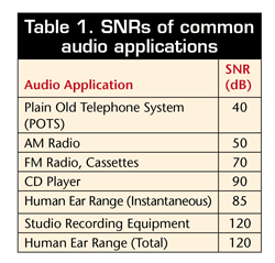
The terms dynamic range (DR) and signal-to-noise ratio (SNR) are used intermittently by audio engineers to describe the quality of an audio signal. Though they may seem equal, there are subtle differences in their definitions and measurements.

DR can be defined as the ratio of the loudest to smallest signal amplitude that can be simultaneously produced or measured. Hence, for a device to have good audio quality, it should have a large dynamic range. This means that it should dynamically or simultaneously be able to produce small and large perceivable amplitudes. In digital audio, this ratio is limited to the bit resolution:
DR=20log10 (2N ) approx. 6xNdB, where N = effective number of bits
Example: for 16-bit CD audio, max DR+20log10 (216 ) approx. 96 dB
SNR can be defined as the ratio of the largest undistorted signal level to noise level during steady state, the noise being measured when no input signal is present. Hence, it is a good indication of the system’s idle-channel noise, which produces unwanted hiss from the device:
SNR(dB)=10log10 (Psignal /Pnoise )= 20log10 (Asignal /Anoise )
Total harmonic distortion
Total harmonic distortion (THD) is the ratio of the sum of the powers of all harmonic components to the power of the fundamental:
THD=∑Harmonic Power/
Fundamental Power=
P2 +P3 +P4 +…/P1 2 +V2 2 +V3 2 +V4 2 +…/V1 2
THD + N, which includes total harmonic distortion and noise, is much more common:
THD + N=∑Harmonic Power+Noise Power/Total Output Power
THD + N is a key parametric of signal quality. Output power is meaningful only when you specify the level of distortion it is measured at (typically 0.01%, 0.1%, 1%, or 10%).
Weighting and clipping
Weighting in audio measurements is used to replicate the profile of the human ear by emphasizing certain mid-frequencies and attenuating very low and high frequencies to which the ear is normally insensitive. A commonly used weighting filter is A-weighting, which emphasizes frequencies between 3 to 6 kHz. A-weighted SNR is measured in decibels (dBA).
Clipping
When an amplifier is pushed beyond its voltage supply rail, the signal will clip. This nonlinear phenomenon manifests itself in the form of audible distortion. It also results in the amplifier producing more power under the curve and the resulting high current can overheat the speaker voice coils. Also, clipping produces strong harmonics in the high frequency range that can damage tweeters.

Fig. 1. When an amplifier is pushed beyond its voltage supply rail, the signal will clip.
AGC/DRC
Automatic gain control (AGC) detects audio levels and uses feedback to increase/decrease the gain to achieve the desired output amplitude. If the input signal is small, the AGC increases the PGA gain. If the input signal is too large, the AGC decreases the PGA gain. By limiting the amplitude range of the output signal, a more uniform signal level can be produced which is compressed to a smaller yet louder amplitude band. This is often referred to as dynamic range compression (DRC).
AGC/DRC has several advantages: louder average volume, improved audio quality (lower distortion), and protection of speakers. An example is the night-time mode in home theater systems. When playing movies with a high dynamic range, the volume has to be increased to hear the dialog, but may be too loud when the background music is heard. AGC/DRC compresses the soundtrack so that all audio content is closer to the same level.
Power supply rejection ratio
Power supply rejection ratio (PSRR) is a measurement of the device’s ability to reject noise from the power supply rail. Noise at the supply rail consists of noise generated by the power supply itself, coupled noise and noise from fast current transients:
PSRR = 20log10 ∆ Supply Voltage/∆ Output Voltage
High PSRR prevents noise from entering the circuit, and reduces the need for extremely clean power supplies, which increase cost. The common use of switching supplies also causes noise and requisites good PSRR. Many think of a battery as a clean dc supply, when in reality they can be quite noisy as current is drawn across the internal battery impedance and PCB power traces. Noise can also be coupled into a battery-powered system and hence PSRR is an important parameter in such devices as well.
Common-mode rejection ratio CMRR) is a measurement of the device’s ability to reject common-mode noise, usually at its inputs:
CMRR=20log10 ∆ Common Mode Input Voltage /∆ Output Voltage
Amplifier classes
Various classes of amplifiers exist such as Class A, Class B, Class AB, Class C, Class D, and more (see Fig. 1) . They are classified primarily based on the segment of the signal cycle during which the amplifier output devices conduct current.
Class A amplifiers have a 360° conduction cycle implying that each output device conducts current through the entire signal cycle. These amplifiers have the greatest linearity (assuming the output devices have enough voltage headroom), but are also very inefficient as a lot of power is wasted across the output devices (15% to 20% efficiency).
Class B amplifiers have a 180° conduction cycle implying that each of the two output devices conducts current for 50% of the signal cycle. This amplifier faces the issue of cross-over distortion, which occurs between the points when one output device stops conducting and the other device starts conducting.
Class AB amplifiers are a trade-off between Class-A and Class-B amplifiers and have a conduction cycle of more than 180°, but less than 360° (50% to 100% conduction cycle). This results in a balance of good linearity and power efficiency (40% to 50% efficiency). These amplifiers are very popular in audio applications such as cell-phones, notebook PCs, and many handheld devices.
Class C amplifiers have a conduction cycle which is less than 180° implying that each of the two output devices conducts current for less than 50% of the signal cycle. This results in poor linearity, but higher power efficiency. These amplifiers are popular in applications that require amplification of a single frequency such as RF.
Class D amplifiers are switching amplifiers that typically use pulse-width modulation (PWM) techniques to achieve high-power efficiency (85% to 90%). Very little power is wasted across the output switches which results in the high efficiency. Hence, these amplifiers are widely used in low-power applications such as battery-operated devices.
The output profile looks like a varying duty-cycle pulse, but a lossless LC filter filters out high frequencies and reproduces the audio signal. In reality, the filter response of the human ear would inherently attenuate the high frequencies.
Other classes of amplifiers also exist such as Class G and Class H.
DirectPath architecture: Cap-less vs. cap-free
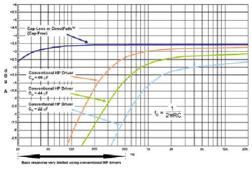
Conventional audio amplifiers have the output terminals biased at half of the supply voltage (VDD ), which can result in wasted dc current into the load even when there is no input signal. Hence, dc-blocking output capacitors are normally used to prevent this dc voltage from reaching the speaker terminals.
These capacitors typically range from 22 to 220 μF, and result in wasted board area as well as cost. Using small capacitors to save board area and cost can result in degradation in bass response and audio quality. This is caused by the single-pole high-pass response created by this dc-blocking capacitor and the load resistance: the smaller the capacitor the greater the pole frequency. In addition, the capacitor-ESR results in power wasted across this capacitor and reduces the overall efficiency.
Two architectures are currently used to eliminate these unwanted output capacitors and they are based on removing the voltage drop across the load terminals.

Fig. 2. Bass response is very limited using conventional headphone (HP) drivers.
Capless architecture. The device provides an additional bias of VDD /2 (known as VMID ) that is applied to the second terminal of the headphone/speaker load, which otherwise is connected to ground. This is commonly known as a virtual ground and equates the potential on both terminals of the load.
Cap-free architecture. The amplifier’s output terminals are biased at true ground with the help of a charge-pump, which creates a negative supply rail for the device circuitry. Thus, both terminals of the load can now be connected to ‘true ground’ potential. Cap-free designs have the advantage of connecting to other devices using the same ground potential such as a microphone in a wired headset.
Interfaces
Inter-Integrated Circuit (I2 C) is an in-the-box serial data communication. It is a two-wire, bidirectional serial bus and is designed for simple, efficient control applications. The I²C bus consists of two active wires: the bidirectional serial data (SDA) line; and the bidirectional serial clock (SCL) line. Transfer speeds vary from 100 kbits/s to 3.4 Mbits/s.
Serial Peripheral Interface (SPI) is an in-the-box serial data communication. It uses a full-duplex, 4-wire serial synchronous serial data link and has higher throughput than I²C.
Inter-IC-Sound (I 2 S) is usually an in-the-box serial interface used for audio communication. It is a uni-directional serial interface developed for digital audio to enable easy connectivity and is often used to transport audio between a digital signal processor (DSP) and coder-decoder (codec). I2 S signals consist of a three-wire serial bus line: a bit-clock line; a left/right clock line (also called word select); and a third line carrying alternating left and right stereo audio channel data.
Sony/Philips Digital Interface Format (S/PDIF) is an out-of-the-box serial audio communication. It is one of the most popular standards for interconnecting digital audio equipment and may be used for digital data transmission over long distances. ■
Advertisement
Learn more about Texas Instruments


