Industrial control systems are ubiquitous and integral to social infrastructures such as electric and water utilities, and our oil/gas, chemical, pipeline, and transportation systems. Not surprisingly, given the violence reported somewhere in the world, the security of these distributed control systems (DCS) or supervisory control and data acquisition (SCADA) systems has become critical. An attack on these DCS would be potentially more disastrous than an attack on computer systems, simply because DCS and physical plants have a direct and immediate impact on our well-being and day-to-day lives.
Since the discovery of the Stuxnet worm just a few years ago, we have become more concerned and more vigilant about the security of our critical infrastructures and the DCS systems which control them. While there are a lot of moving parts to the Stuxnet story, it is known that the worm spreads via a USB thumb drive. Architects of industrial systems must now take deeper security measures. However, most recent security measures have only aimed at protecting the confidentiality, integrity, and availability of a system and its related networks. A critical area has been overlooked for too long: the sensor card or field I/O module.
We will speak generally of DCS systems in this article, readers should know that SCADA systems are always implied too. Further, the term “sensor card” refers to all field sensor devices, I/O modules, and smart sensors.
The networked sensor card
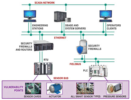
Figure 1 shows the architecture of a typical DCS/SCADA system. At the bottom layer of the system is the sensor card that monitors temperature, humidity, motion, liquid level, water flow, smoke, door activity, power failure, or current and issues alarms to the system.

Figure 1: Typical DCS/SCADA system architecture with the sensor at the bottom level.
Although not usually considered a potential attack target, many believe that the sensor card should be. The sensor card is upgraded or replaced by service technicians more often than other system units. One advantage of using a standard communication interface protocol is that a service technician can use sensor replacement cards from multiple vendors in their DCS system. Here is where the benefit of multiple sources can become a liability and vulnerability.
In most cases there is no effective way to ensure that a replacement sensor card has not been spoofed, cloned, or counterfeited. But there is a way to correct this problem: add a secure authentication IC to the sensor card. This component completes an effective secure system which authenticates each sensor card to the highest controlling level of the DCS/SCADA network. An asymmetric signature scheme like an elliptic curve digital signature algorithm (ECDSA) is beneficial for such an authentication.
ECDSA cryptography secures a sensor card
It is common for consumer disposables to be attacked by a variety of sophisticated die-level methods attempting to extract secure data, reverse device settings, or disrupt the operation to compromise system security or just to clone it. The industrial sensor card is a similar, often vulnerable target. To provide the highest affordable protection against an inevitable attack, the secure system’s secure IC must employ proprietary die-level physical techniques, circuits, and crypto methods to protect the private key, control signals, and other sensitive data.
There are a number of secure authentication ICs available. Preferred solutions use the elliptic curve digital signature algorithm (ECDSA) – an efficient and secure crypto-algorithm technology. It allows mathematical constructions from number theory and algebraic geometry. An optimal ECDSA implementation will use public key-based security and a certificate infrastructure along with a digital signature for authentication. The programmable logic controller (PLC) first verifies the certificate of the sensor card and then performs a digital signature exchange to confirm authorization for this system.
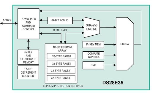
ECDSA public, key-based cryptography authenticators (like the Maxim DS28E35 DeepCover authenticator) perform these security procedures very effectively and with little effort. They use a FIPS 186-based ECDSA public-key crypto-authentication method and have a 1 Kbit user-programmable EEPROM storage space and additional memory for the public key and certificate. They also use a decrement-only counter, a private-public key-pair generator, a hardware random number generator (RNG), and memory that can be partitioned into areas that are read and/or write protected.
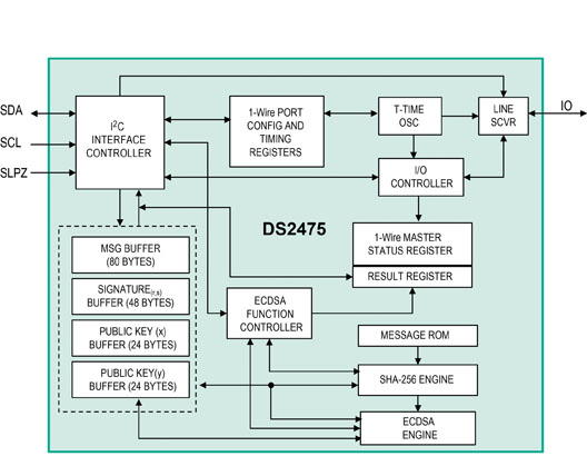
ECDSA involves elliptic curve operations over finite fields, which is a mathematically intensive operation to implement. While the authenticator IC resides on the sensor card, the PLC must also be able to compute a digital signature. This capability comes at the cost of much greater computational complexity for the PLC’s host microcontroller, for which computation time is often a scarce resource. A companion coprocessor IC, such as the DS2475, can be placed adjacent to the host microcontroller on the PLC module to offload the ECDSA computation. The coprocessor does not need any secret data. The functional block diagrams of both the DS28E35 secure authenticator and DS2475 coprocessor are show in Figure 2.

 Figure 2: The functional block diagrams of the DS28E35 and DS2475 coprocessor.
The coprocessor implements a ECDSA engine for public-key signature verification that is also based on NIST FIPS 186. The authenticator and coprocessor implement their public-key signature using both Curve P-192 and a NIST FIPS 180 SHA-256 engine for setting up the input data to their respective ECDSA computation engine. On power up, the PLC can now verify the authenticator’s certificate and, thus, positively identify the sensor card as part of the ecosystem. The PLC then confirms that the public key stored inside the authenticator is valid. An IO-Link communication protocol connects the two subsystems, but the protocol can be any of the many that exist today.

Figure 3. Secure sensor card/module authentication setup features the DS28E35 DeepCover secure authenticator communicating to MCU over a 1-Wire interface.
ECDSA challenge-and-response authentication
In its simplest form, the ECDSA challenge-and-response authentication principle is a secure hand-shaking scheme in which the PLC presents a question (the challenge), to which the sensor card must provide a valid answer (the response) in order to be authenticated. Having received the PLC’s challenge, the sensor card’s response is a valid digital signature. If the PLC cannot verify the returned signature, meaning that the sensor card gets the answer wrong, then the PLC will reject the sensor card as unauthorized to the system. This rejection could simply mean that data provided by this particular sensor card will all be rejected and perhaps not sent up the chain to the system operators to ensure that the questionable data do not affect future system-control decisions.
The major components of this ECDSA authentication scheme include the 256-bit random challenge, the sensor card’s authenticator (i.e., the DS28E35), ROM ID, an RNG, the private key, and some other data elements. The key pair (public/private) can be generated externally outside the authenticator chip and loaded, or it can be computed inside the IC. When the key pair is generated inside the authenticator, the private key can never be read or be removed from the device. However when an outside key pair generator is used, a strong key-management scheme is required to keep the private key from ever being compromised.

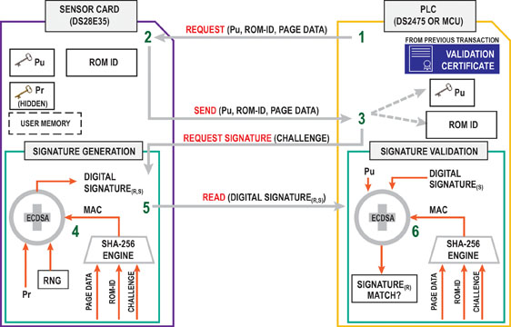
Figure 4: ECDSA challenge-and-response authentication transaction sequence. A simple example assumes that a certificate verification was completed prior.
Immediately after the sensor card has been installed and powered up, the following sequences of events take place between the PLC and the sensor card. The ECDSA challenge-and-response authentication transaction sequence is illustrated in Figure 3 as follows:
- The PLC reads out the sensor card’s ROM ID, public key, page data, etc.
- The sensor card sends the requested data
- The PLC generates and sends a random challenge to the sensor card.
- The sensor card’s authenticator (DS28E35) computes an ECDSA signature of the challenge provided by the PLC. The challenge, page data, ROM ID, and some other data elements are hashed to get a message authentication code (MAC). The MAC is then fed into the ECDSA engine along with the private key (Pr) and a random number to create the ECDSA signature.
- The PLC reads the digital signature and verifies it using the public key. The PLC‘s secure coprocessor (DS2475) uses the same items, including the same memory data, ROM ID, and data elements to compute the same MAC.
- If there is a signature-match the card is authenticated.
Advertisement
Learn more about Maxim Integrated


