BY ROBERT CHAO
President and CEO
Advanced Linear Devices
www.aldinc.com
Supercapacitors used in a series are gaining prominence as energy storage devices for a number of applications because of their versatility, utility, and durability. This technology is a relative new addition to many applications, and circuit designers have often used traditional components and circuits to support supercapacitors configured in a stack or series. However, next-generation components such as auto-balancing MOSFET arrays have the potential to revolutionize supercapacitor module design by optimizing performance by protecting against overvoltage, extending component life, reducing board space, and reducing cost of circuit design.
Supercapacitor auto-balancing (SAB) MOSFETs change the game in active leakage current regulation and self-balancing supercaps connected in a series stack. The ALD8100xx/ALD9100xx SAB MOSFETS, for example, made with precision EPAD technology from Advanced Linear Devices, offer advantages to commonly used auto-balancing schemes using passive resistors or operational amplifiers.
Old designs
Older schemes based on traditional components contribute to continuous power dissipation in supercaps due to linear currents at all voltage levels. Differences of leakages in series-connected supercaps make it difficult to control the voltage level in each cell. Leakage differences can cause one or more supercap to exceed rated voltage over time, which can overstress cell materials, reduce lifespan, and eventually cause rupture and catastrophic failure.
The new supercapacitor auto-balancing MOSFETs have unique electrical characteristics for active continuous leakage current regulation and self-balancing for stacked or series-connected supercaps because they dissipate near-zero leakage current, practically eliminating extra power dissipation. The SAB MOSFET provides voltage balancing for a supercapacitor by increasing its drain current exponentially when voltages increase. The MOSFET can also decrease drain current exponentially when supercap voltages decrease. When a supercap is configured in a stack, each cell can be charged to within 90% of the desired voltage limit by configuring the SAB MOSFET to turn off, thus cutting leakage current to zero.
Designers traditionally turn to op-amp-based solutions for supercap stacks. These solutions often require several components to precisely control overvoltage. Additionally, op amps burn considerable amounts of power and take up board space. Since many applications for supercapacitor modules are cost-conscious, such as automotive or consumer, an important design consideration is to reduce the bill of materials by minimizing component count and board space.
Many board designers use resistors or actively balance circuits for modules. But switching to auto-balancing MOSFETs may require foresight to unlock the full potential. If a designer used an SAB MOSFET as a shunt regulator across one cell to prevent overvoltage with an energy harvester, then it is possible to achieve good utility. However, if the one device is used merely as a shunt regulator to protect a single cell against overvoltage, the full performance potential of the MOSFET will not be realized.
The ALD8100 and ALD9100 family of devices require some design work to be used optimally as an over-voltage regulator for cell balancing circuits. However, the MOSFET only dissipates power at or over the targeted regulation voltage. Because each cell has its own over-voltage limiter, cells connected in series self-balance and performance of each is not affected much by the input characteristics of the energy harvester. At less than 0.3 V below the target voltage, the power dissipation by the MOSFET is essentially zero, making it ideal for energy harvesting applications.
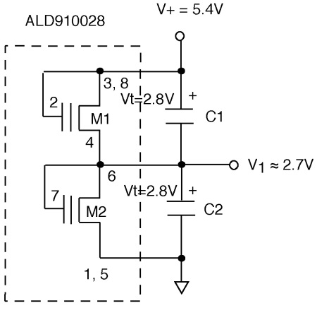
Fig. 1: Example of ALD910028 connection across two supercapacitors in series
When SAB MOSFETS are designed as a cell balancer, they protect against over-voltage depending upon V-I characteristic, but they can also balance to the midpoint. This is important to prevent premature aging. For example, a two-cell ultracap using 2.6 V MOSFETs across each cell, can be charged to 4 V. One cell might achieve 2.65 V and the other at 1.35 V, which would lead to premature aging compared to having two cells at 2 V each.
As a two-cell balancer, the MOSFET nominal threshold voltage works best if an operating target supercap voltage is selected. For example, if the two cells are charged to 4.6 V, each with an ALD810023 device, then than one cell is charged to 2.35 V and the other is charged to 2.25 V, when the difference in leakage between one supercap cell is 10 times that of the other. If the relative leakages of the two supercap cells are closer to each other, then the cell voltage would perhaps settle to 2.32 V for one cell and 2.28 V for the other cell. The active MOSFET shunts only excess leakage current of one cell over another, whichever is greater and thus, it would enable balanced cell voltages.
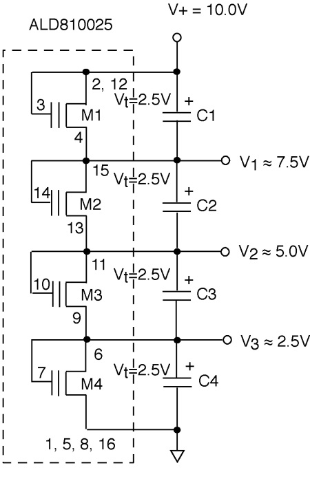
Fig. 2: Example of ALD810025 connection across four supercapacitors in series
For charge voltages in this example to be 4.0 V instead of 4.6 V, one of the MOSFETs can act more like an overvoltage clamp, thereby limiting the two cell voltages to 2.20 and 1.80 V, respectively (or 2.15 and 1.85 V), with actual voltages depending on the relative and absolute leakages of each supercap. This will still protect the supercap that is most vulnerable to overvoltage. The other MOSFET in the package is completely turned “off,” resulting in zero additional leakage and zero additional power.
A more appropriate device for a charge voltage of 4.0 V would be using ALD810021 (for maximum supercap leakage of 1 μA) when each MOSFET is rated at 2.1 V and the overall charge voltage is 4.0 V. Depending upon the actual relative leakages of each of the two supercaps, the resulting voltages are likely to be one of three cases: 2.10 and 1.90 V, 2.05 and 1.95 V, or 2.00 and 2.00 V. In the case of 2.10 and 1.90 V, then the 2.10V supercap has a leakage current that is 100 times less than that of the 1.90 V supercap. The MOSFETs connected across each supercap have 1.00- and 0.01-μA drain currents, respectively. In the case when the supercap voltages are 2.05 and 1.95 V, then the leakage current between the two supercaps is about 0.3 and 0.03 μA, a ten to one ratio. If the supercap voltages are 2.00 and 2.00 V, then each cell has very nearly equal leakage currents and each MOSFET would conduct about 0.1 uA.
About the Author
Robert L. Chao founded Advanced Linear Devices, in 1985 and has been a leading authority in the analog semiconductor industry for more than 30 years. Before that, he was one of the founders of Supertex, where he was instrumental in inventing the analog circuitry that enabled the home smoke detector.
Advertisement
Learn more about Advanced Linear Devices


