Design Considerations
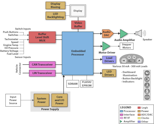
The instrument cluster is the main means to display information and status of the vehicle systems and drive conditions. This includes gauges for various parameters, indicators and status lights but also displays and acoustical effects.
Power management: The power supply is connected to the 12V or 24V board net and regulates down/up to voltages for DSP, uC, memory and ICs and functions like stepper motors, communication interfaces, display biasing and back lighting. The need for many different power rails makes the design of the power supply a critical task when trying to design for size, cost and efficiency. Linear regulators with low quiescent current help reduce battery leakage current during standby operating modes (ignition off), are load dump voltage tolerant for directly battery connected devices, and need low drop out and tracking for low battery crank operation.
Beyond providing increased conversion efficiencies, switching power supplies provide EMI improvement with slew rate control of the switching FET, Frequency hopping, spread spectrum or triangulation method for attenuation of peak spectral energy, Low Iq, soft start for power sequencing and in rush current limitation, Phased switching for multiple SMPS's regulators to minimize input ripple current and lower input capacitance, higher switching frequency for smaller components (L and C's), and SVS functions for brown out indications.
Communication Interfaces: Allow data exchange between independent electronic modules in the car, the remote sub modules of the infotainment system as well as external devices like USB memory or video sources. High Speed CAN (up to 1Mbps, ISO 119898) is a two wire, fault tolerant differential bus. With a wide input common mode range and differential signal technology it serves as the main vehicle bus type for connecting the various electronic modules in the car with each other. LIN supports low speed (up to 20 kbps) single bus wire networks, primarily used to communicate with remote sub functions of the infotainment system. LVDS interfaces are used to transfer large amounts of data via a high speed serial connection to an external location like a video screen.
Load Drivers: The main load types in a Cluster are the stepper motors used to operate the gauges and the various indicator and back light sources (mostly LEDs). The Stepper motor drivers are typically integrated in the uC. LED drivers are typically multi-channel devices with serial interfaces to the uC or Darlington arrays. For gauge and dash backlighting an SMPS based constant current LED driver offers the best efficiency as well as excellent brightness control.
Display: Almost all clusters have displays, ranging from small dot matrix up to several inch large color, high resolution LCD displays. Depending on the display type, a power supply solution for the display biasing is required on top of the LED or CCVF drivers for backlighting. The video information is either sent directly from the uC or via a LVDS interface depending on the size of the display.
Microcontrollers: Aimed at driver information and cluster systems, need to drive multiple stepper motors and displays ranging from LCD segment displays to DVGA TFT displays. These devices need to integrate high performance CPU cores, multi-channel DMA engines, TFT controllers, and a fast external memory interfaces to provide enough system performance to implement feature rich graphic functions such as anti-aliasing, texturing, chroma-coding, animation, etc. The MCU also needs to high enough performance speed to service the stepper motors in real time.
Click here for Guide
Download Full Block Diagram Below
Advertisement

Learn more about Texas Instruments


