By Wilson Lee, senior manager, marketing, Tektronix, www.tek.com
The global market for high-brightness and high-power LEDs is forecast to reach $27.5 billion by 2024, with much of the growth coming from the automotive sector, where demand is growing at more than 10% per year, according to a recent report from Hexa Research. Much of this growth, encompassing everything from consumer devices to commercial applications, is due to the fact that high-brightness LEDs exhibit superior luminosity compared to traditional LEDs and lower energy consumption than alternative lighting sources.
Although there is some distinction between a high-brightness LED (HBLED) and a high-power LED, from a test perspective, they are essentially one and the same. An HBLED is considered to be a light-emitting diode that produces over 50 lumens. A high-power LED is defined as one consuming more than 1 watt in power. Ultimately, the distinction comes down to different characteristics or parameters.
The higher power is what delivers the sought-after brightness but is also what can cause problems in testing if engineers overlook the risk of inrush current. All too often, excessive inrush current can be applied inadvertently during testing and can potentially lead to damage of the LED that you’re attempting to test.
This article looks at what can happen when too much inrush current is applied during LED testing, why it’s a problem, and how to prevent it.
HBLED overstress
An LED is a two-terminal semiconductor device. A diode turns “on” at a characteristic voltage (Vd ) in the forward bias operating region when an avalanche of electrons and electron holes starts to recombine. During this recombination process, one of the properties of an LED is the release of energy in the form of photons, which cause the LED to illuminate. The I-V characteristic of a diode in the forward bias region is depicted in Fig. 1 , where Vd is the ON voltage of the diode.
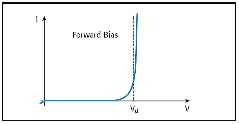
Fig. 1: Typical I-V curve of a diode.
Although LEDs can be driven with either voltage or current, current is the preferred method because LED brightness is proportional to its drive current. As the I-V curve in Fig. 1 indicates, a small change in voltage results in large variations in current, which will lead to drastic and undesirable variations in LED brightness.
In addition, temperature and aging can cause Vd to drift over time. Again, this small voltage drift will likely cause unwanted current variations. Furthermore, driving LEDs with excessive amounts of current can result in irreversible damage and lead to much shorter device lifetimes. Therefore, regulating the drive current at appropriate levels in LEDs is critical.
Inrush current is a common phenomenon that overstresses LEDs. An LED can be modeled as a parallel R-C network, which means that the device is instantaneously a short circuit when a voltage is applied across the device’s terminals. This instantaneous short circuit results in an inrush current — a short-duration startup current with far greater magnitude than the LED’s steady-state operating current.
Hot switching
Let’s take a look at how introducing an LED to an energized circuit or “hot switching” the LED can lead to an inrush current of damaging magnitude. As shown in Fig. 2 , when the switch is open, the voltage at the power supply is maintained at the rated voltage of the LED.
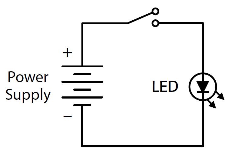
Fig. 2: Test system schematic.
However, as soon as the switch closes, the charge stored at the output of the power supply and the wires flows rapidly into the LED until the power supply starts to regulate the flow. In Fig. 3 , the LED turn-on voltage is shown by the yellow waveform and current by the blue trace. When powered by a power supply in the traditional constant voltage (CV) mode, a notable transient current peak is visible.
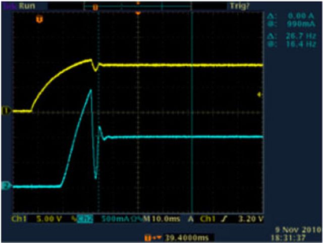
Fig. 3: A transient current peak is shown by the blue trace when the LED is powered by a power supply in traditional constant voltage mode.
When testing LED designs, engineers typically use a benchtop power supply to drive power to the device precisely while they are taking measurements. Too often, engineers have the settings wrong or they use a power supply that isn’t fully controllable and end up destroying their devices. But this is entirely preventable.
Constant current mode
A growing trend in power supply design is the addition of a constant current (CC) mode beyond the traditional programmable CV mode. When a power supply operates in CV mode, voltage is regulated while the current may vary. With CC power supplies, the current delivered to the device under test is independent of the load value.
This results in the behavior captured on the oscilloscope in Fig. 4 . When the power supply is operating in the CC mode, the current is regulated and supplied to the load while the voltage output may vary.
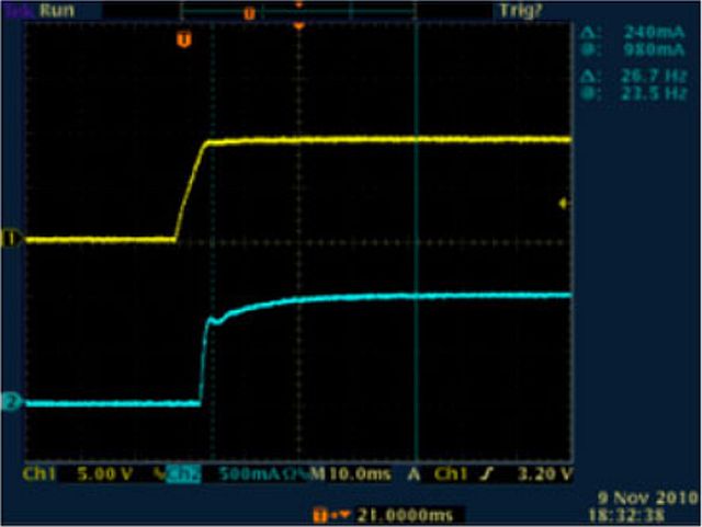
Fig. 4: In constant current (CC) mode, a power supply such as a Keithley Series 2260B is capable of keeping the current input to the LED under control until the LED reaches its ON voltage.
The use of CC mode eliminates the need for external controlling circuitry and simplifies the approach needed to “soft-start” an LED. The power supply itself is capable of keeping the current input to the LED under control until the LED reaches its ON voltage. By removing the possibility of transient inrush current, you are protecting the LED from related damage. With current-limiting mode in place on your power supply, testing HBLEDs is safe and easy.
About the author
Wilson Lee is senior manager, marketing at Tektronix. Prior to joining Tektronix, Wilson has had over 25 years of technical marketing and technical sales leadership roles — with manufacturers such as CTS Electronic Components as well technical/value-add distributors such as Richardson RFPD and Premier Farnell. Wilson has heavily focused on design within the RF/wireless, industrial power, and industrial automation market segments. Wilson earned his Bachelor of Science degree at Cornell University. While living in New York, Chicago, and Asia throughout his career, he currently resides in Greater Portland, Oregon.
Advertisement
Learn more about Electronic Products MagazineTektronix


