Winter is coming quicker than we may hope, bringing with it the reoccurring nuisance that is the frozen water pipe. As most homeowners will agree, frozen water pipes are a huge pain in the neck, ruining plumbing systems and cutting off precious water supply in the throes of winter—if you live in a particularly frigid environment, you’ll know exactly what I mean. Fortunately, there are several preventative measures you can take — such as insulating your pipes and leaving the water dripping — but since we’re makers and this is the 21st century, we may as well spruce things up by throwing-in a homemade temperature sensor. Here comes Arduino to the rescue.
Required materials/tools:
Arduino UNO microcontroller
Thermistor
10 kohm resistor
Jumper wires
LED
Piezo buzzer
Project enclosure
Printed circuit board
Glass of ice water
Plastic bag
Step one: Build a temperature sensor
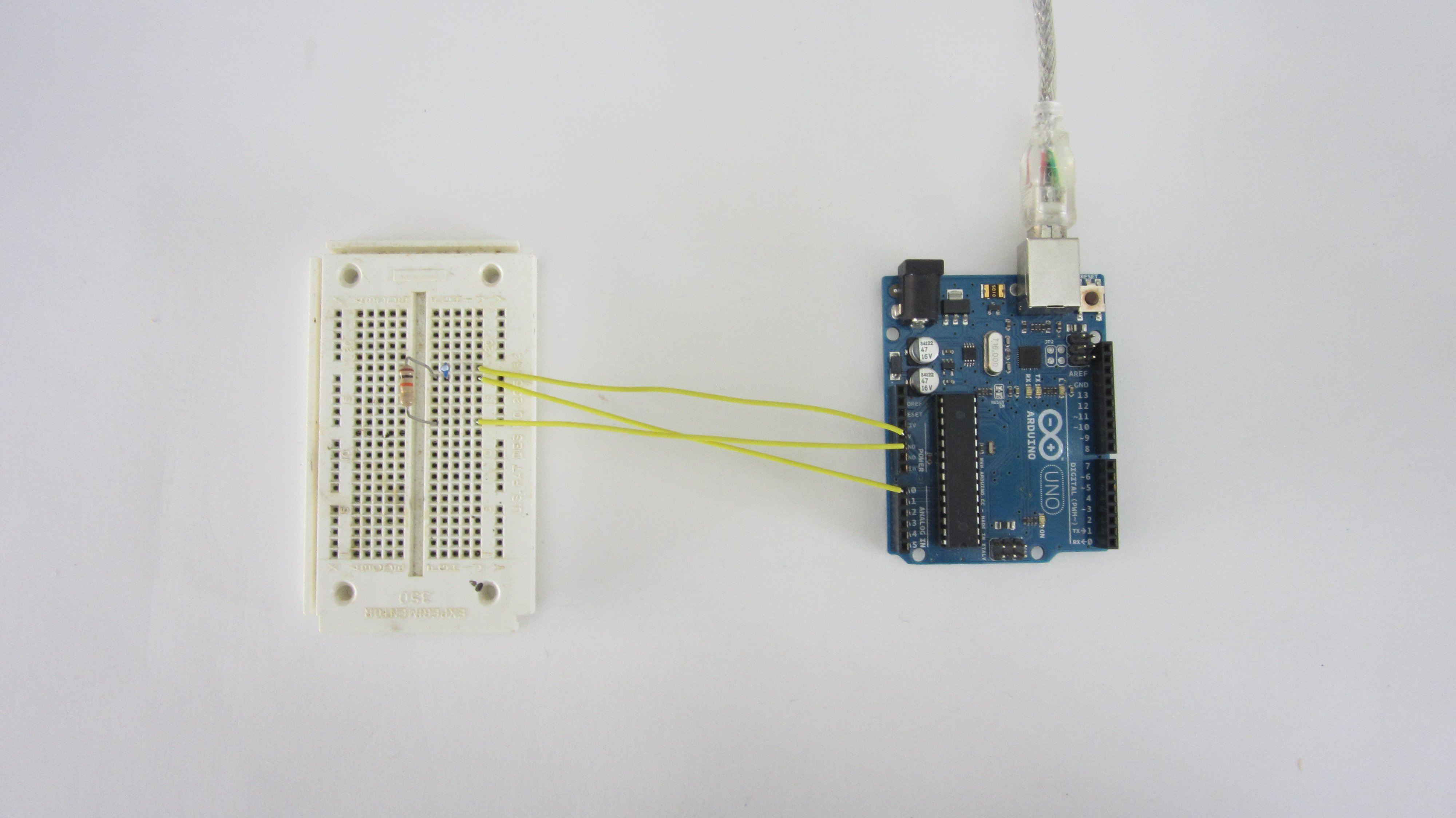
The temperature sensor in question is made by connecting a temperature-dependent resistor (thermistor) and a fixed resistor together to form a voltage divider. As the temperature changes, so too does the resistance of the thermistor, which in turn causes the voltage between the two resistors to also change; this can create a measureable parameter using an Arduino-powered temperature sensor.
To construct the sensor, connect one lead of the fixed resistor to the GND pin on the Arduino and the other lead to an analog input pin. Then attach the other lead of the thermistor to the same analog input pin. We will now be able to use the AnalogRead function to measure the voltage changes. Lastly, use a pair of long jumper wires to insert the thermistor into the wall where the pipes are.
Step two: Set up the Arduino code
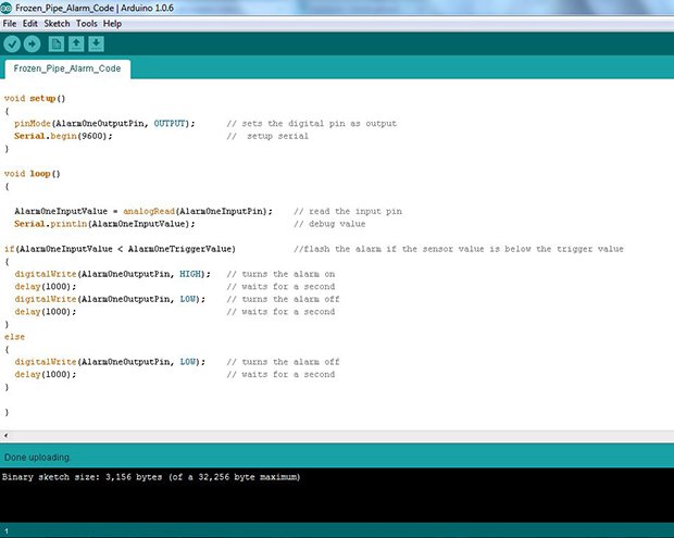
Now it’s time to input the Arduino code. Here is a sample that we may use for the sensor:
int AlarmOneInputPin = 0; // sensor connected to analog pin 0
int AlarmOneOutputPin = 9; // Alarm connected to digital pin 9 int AlarmOneInputValue = 0; // variable to store the value read int AlarmOneTriggerValue = 350; // alarm set value
void setup() { pinMode(AlarmOneOutputPin, OUTPUT); // sets the digital pin as output Serial.begin(9600); // setup serial }
void loop() {
AlarmOneInputValue = analogRead(AlarmOneInputPin); // read the input pin Serial.println(AlarmOneInputValue); // debug value
if(AlarmOneInputValue
}
Step three: Calibrate the sensor
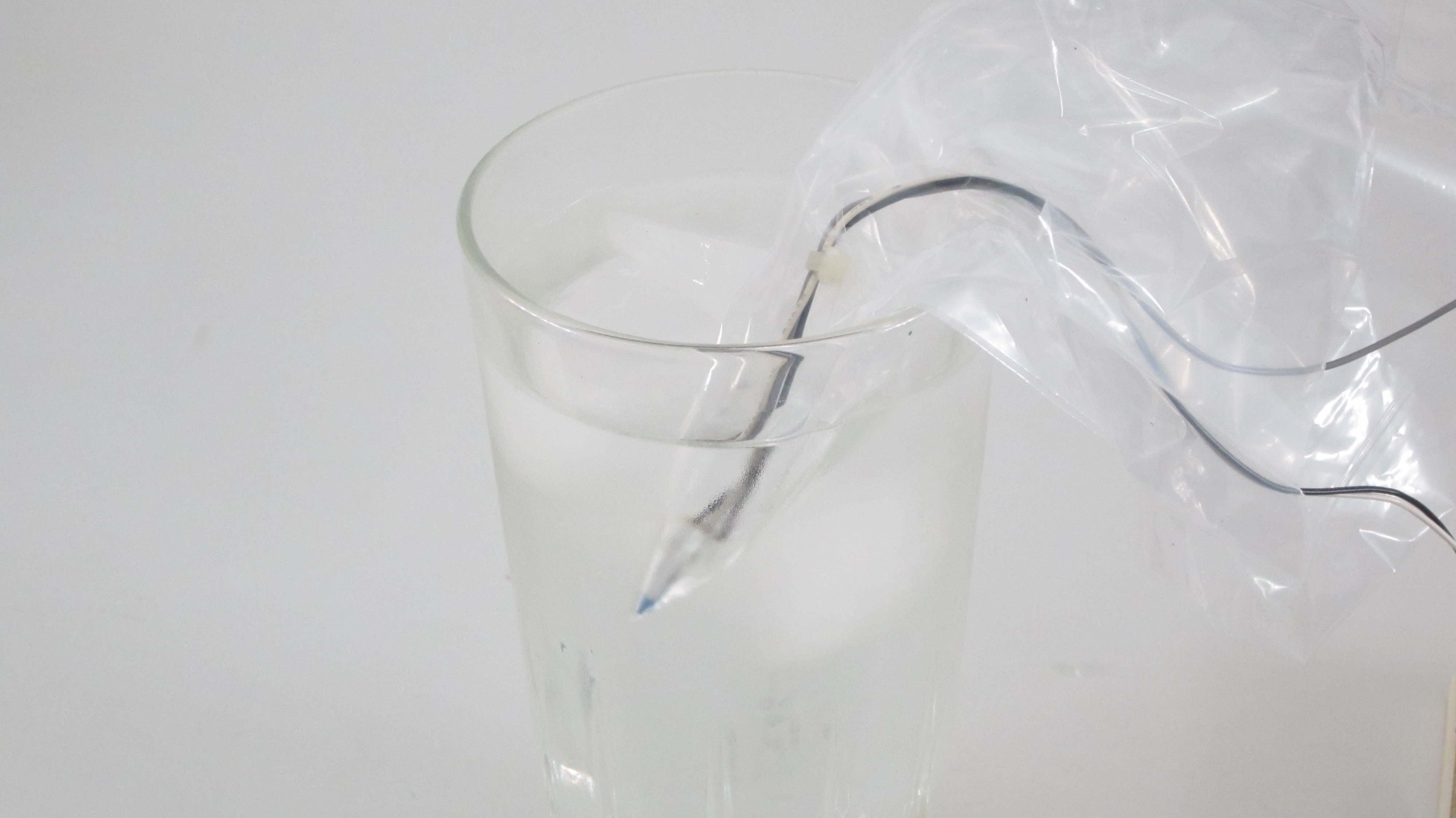
But before we can use the sensor, we will need to calibrate it. To do so, simply retrieve a glass of ice water, insert the thermistor into a small plastic bag, and submerge it. The water should be just above the point of freezing. From there, use the AnalogRead function on the Arduino to measure the voltage connection between the two resistors. The result displayed will range from 0 to 1023, which represents the range from 0V to 5V. If the sensor reads about 300, that means it will read around that same number right before the freezing point, which will be the value used to activate the alarm.
To set the alarm temperature, open the code file and set the value of “AlarmOneTriggerValue” to 300 (or your measured number).
Step four: Construct the alarm
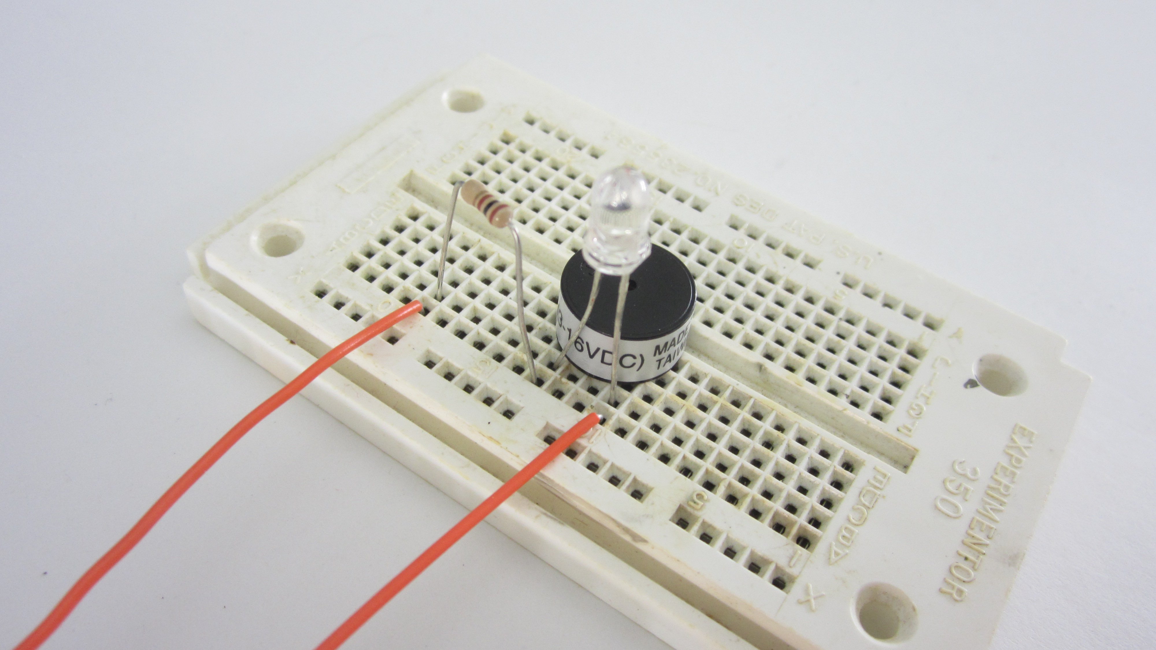
To build the alarm in the most practical manner possible, connect the LED and piezo buzzer in parallel in order to activate both with a single digital pin from the Arduino. Whatever alarm you decide to use, make sure it doesn’t exceed the 40ma maximum output of the digital pins, otherwise you’ll need to set up a driver circuit with a power transistor or relay.
Next, we’ll sample the alarm on a breadboard before, assembling the circuit on a PCB and link it to a small piece of perf board. Connect the negative terminal of the alarm to the GND pin on the Arduino and the positive terminal of the alarm to digital pin 9.
The alarm should now be working on its own circuit board and can be mounted inside a small project enclosure. To fit the parts inside, drill a hole in the center for the LED and cut a slot in the side for the wires.
Step five: Insert the temperature sensor into the wall
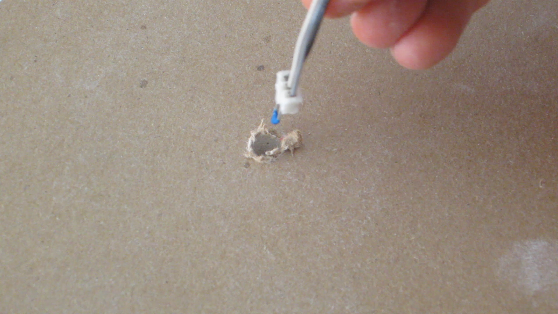
Now that everything is constructed, it’s time to insert the temperature sensor into the wall near the pipes. If there is already a hole in the wall around your pipes, simply slide the sensor right in there; if not, you’ll need to drill a small one as close to the middle of the pipe as possible.
Once the sensor is properly inserted into the wall, try to position it close to the pipes. If necessary, place a piece of tape over the hole to help hold it in place.
Step six: Use the sensor to monitor your pipes
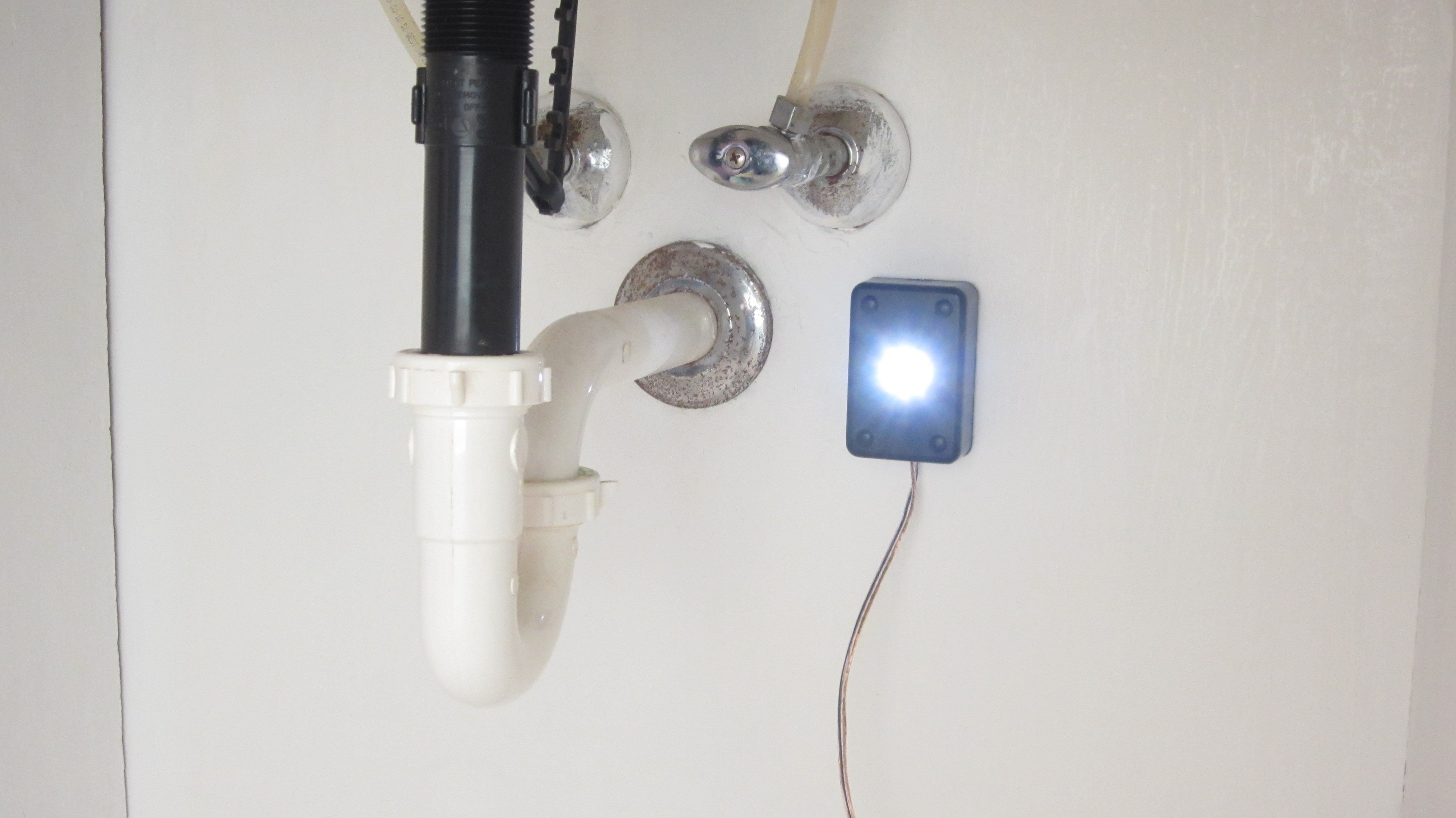
The final step is to mount the alarm in a noticeable location. The sensor is now ready to be used to monitor the pipes. Remember, we can add as many sensors as we have analog input pins on our microcontroller, which would allow a single Arduino Uno to monitor up to six sensors. It’s even possible to use this type of sensor to automatically control an electric pipe heater; all we need is a PowerSwitch tail or relay driver.
There you have it: a peace of mind solution to ensuring your pipes don’t freeze this winter.
Source: Makezine
Advertisement
Learn more about Electronic Products Magazine


