Balancing power parameters in LED applications: Part 2 — Cost-effective solutions for LED designs
To meet power conditioning standards and the market requirements for load control there are tradeoffs to be made to maintain good EMI, power factor and efficiency
BY ALEXANDER CRAIG
Principal Engineer
Fairchild Semiconductor
www.fairchildsemi.com
Low-power LED solutions typically consist of a single-string of LEDs or a single input and output control point for the LED driver. These drivers must perform the basic functions of any LED power supply, such as power conditioning and conversion and load control. In Part 1 ( http://www2.electronicproducts.com/Balancing_power_parameters_in_LED_apps-article-fapo_Fairchild_may2012-html.aspx) we compared different methods of achieving good power conditioning and conversion for low-power isolated flyback and nonisolated buck-boost designs shown in Figs. 3 and 3a below. In this article we will present the load control method for the FL7730 and FL7732 solutions. There is a significant interplay of load control when dimming and power conditioning, so in order to meet power-conditioning standards and the market requirements for load control we will outline some tradeoffs between maintaining good EMI, power factor and efficiency, With achieving good load control, such as fault protection, constant current control, LED current ripple and dimming.
Before we can address dimming we must first have tight constant load current control at full power. As previously explained, Fairchild’s TRUECURRENT technology control block allows the engineer to maintain a ±3% CC accuracy, but this is an average LED current that would be measured with a dc-current meter. When one looks at the LED current with a current probe and a oscilloscope at a time scale on a few ms/div, an ac-ripple current at 2x line frequency on the average LED current measured with a dc-current meter can be seen. Therefore, selecting an allowable ripple current is necessary to optimize the cost and performance for the design. Too high a ripple current will negatively affect the LED, LED-driver life time, and efficiency. As with any high power factor flyback or buck-boost, some energy storage is needed to lower the ripple current. A solution with a passive or valley fill PFC will incorporate high-voltage electrolytic caps on the primary-side and a low-voltage electrolytic caps on the output to reduce ripple. Some problems with this approach are the valley fill PFC is good for one given line and load operating point. The use on high-voltage electrolytic caps lowers system lifetime. High-voltage input bulk capacitor is the most delicate component which may affect negatively to the total system life time. The factors that lower lifetime in electrolytic capacitors are temperature, voltage, and ripple current.
Long-life, high-temperature, low-voltage electrolytic capacitors are becoming more prevalent. By not using high-voltage electrolytic capacitors we can prolong the system lifetime but we must store enough energy on the low-voltage side of the transformer. Since the energy stored in a capacitor is ½ CV2 for a design with no high-voltage electrolytic capacitors on the primary-side all the energy storage must come from the secondary-side. With a high power factor single-stage approach the control loop has a 20 to 30-Hz bandwidth; this means that the 2x line frequency ripple can pass through the supply and be seen at the output. LEDs with loads that have moderate ripple do not dramatically affect the lumen output. All that needs to be determined is the acceptable ripple current for the design, and then the output capacitance can be calculated from the LED load characteristics and Equation 1 below.
If we assume a LED average current is 0.7 A and we allow a ripple on 20%, we have an Imax out = 0.84 A and a Imin out = 0.56. So, from Fig. 1 , ∆Vout = 14.6 – 13.2 = 1.4 V so using Equation 1 Comin should be greater than 954 µF. A 10% ripple would require a Comin > 2,451 µF.

Equation 1
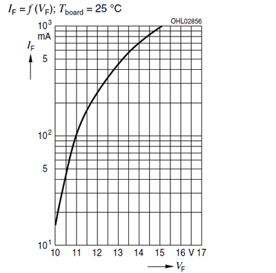
Fig. 1: Vout LED load characteristics at 25C
For a nondimming application a 20% Iout ripple may be acceptable. But is it acceptable for a dimming application? There cannot be a dimming design with so much ripple that the LED light flashes at 2x the line frequency. So a closer look must be given to the LED load characteristics, and the minimum LED current needed to produce the minimum light output must be determined. There needs to be a relationship found on the LED datasheet between light output and current through the LED.
In the example LED load, there are two values that refer to this relationship: The first is the easiest to work with — the minimum IF, listed on the datasheet at 100 mA so with a 20% Iout ripple of 100 mA and 140 mA, Figure 1 gives a ∆Vout = 11 – 11.5 = 0.5 V so using equation 1 Comin should be greater than 446 µF.
The other parameter that refers to this relationship in the form of relative luminous flux, is shown in Fig. 2 , which is set at approximately 700 mA IF for a 10/1 dimming ratio. This graph indicates a Iout of 60 mA, so the same 20% Iout ripple finding VF from Fig. 1 at IF values of 48 and 72 mA. Fig. 1 gives a ∆Vout = 10.5 – 10.75 = 0.25 V; using Equation 1 Comin it should be >458 µF. However, since the 60 mA is less than the minimum IF listed on the datasheet of 100 mA, the light output may flicker even though the LED driver is providing a consistent Iout with 20% ripple. This is not the fault of the LED driver, but a mismatched LED load.
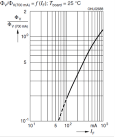
Fig. 2: Relative luminous flux load characteristics at 25C.
The dimming control function for the FL7730 is seen in Figs. 3 and 3a . A simple resistor divider network and RC filter is used to convert the duty cycle of the ac-line voltage into a dc-voltage, which is placed on the dim pin of the FL7730, is shown in Fig. 4 . A two-angle control block is used to offset the current sense measurement and is used as an input to the TRUECURRENT technology calculation block. This is compared to a high level of dimming control to particular dimming angles that would equate to low-rms input voltages. This simple, yet effective, way of controlling the intensity of the LEDs is useful with virtually all forms of dimming controls, even the most difficult, such as TRIAC -based dimming, or the simpler dc-input solution , a PWM input solution, which can be filtered to produce a dc voltage. The relationship between the voltages present on pin 5 of the dim pin can be seen in Fig. 5 .
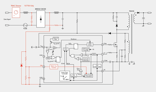
Fig. 3: Dimming control function for FL7730.
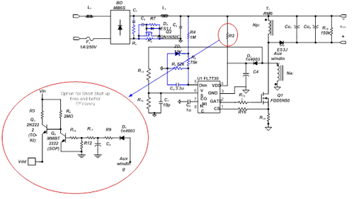
Fig. 3a: Focus on the dimming control function.
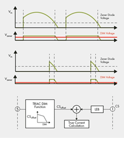
Fig. 4: Simple resistor divider network.
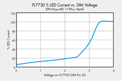
Fig. 5: The relationship between the voltages present on pin 5 of the dim pin.
When dimming, the most challenging issue to overcome is flicker. Of course, flicker is also caused by many issues such as the mismatched LED load and driver IV characters that may also show up flashing at some line load combinations. In these cases the Vdd voltage is either too high or too low and the IC enters undervoltage lockout (UVLO) or overvoltage protection (OVP). Often this is a result on the AUX winding on the transformer being incorrect, adding a resistor between the AUX winding and the Vdd diode may offer some fine tuning of the AUX voltage with only a slight power loss.
The most vexing challenge is the triac-based dimmers. Here, the issue is that these thyristor-based dimmers, which were developed in 1959 and are used in triacs today, have a minimum “holding current” or minimum load in order to stay on. With incandescent lamps this is not much of an issue as the incandescent is basically a resistor and only ~10% of the energy it consumes produces light. However, to get the same amount of light with a new LED bulb much less energy is needed, so you can change the holding current threshold of the triac. For low-power LED lamps some bit of circuitry needs to be added to force the triac to trigger and stay on. This circuitry will also alter the electromagnetic interference (EMI) performance of the supply. Typically, some resistive element is needed in this trigger and hold circuitry and this will negatively affect efficiency, but often improves PF and THD. As the power of the design increases, this circuitry can become easier because the load consumes more power, even when dimmed. With low-power LED bulbs this circuitry can get quite involved, particularly if the intent is to work with every dimmer on the market, each with a different minimum holding current and impedance. Here is where a good product definition with a well-defined dimmer list will greatly help the electrical engineer to produce a cost-effective LED product. The details of the triac trigger and hold circuitry is too complex for the scope of this article so the more triac-based dimming details can be found in application note http://www.fairchildsemi.com/an/AN/AN-9745.pdf.
The FL7730 and FL7732 can satisfy flyback and buck-boost designs. The FL7730 can satisfy TRIAC, PWM or 0 to 10-V based dimming, but the success of any design must start with a well-defined product specification. Some of the key questions to be answered when choosing a solution for a single-string LED application less than 35 W are as follows:
• Is isolation required?
• What is the dimming method?
• Can you define a dimmer list?
• What are the intended LED loads?
• What is the minimum LED current needed to produce the minimum light?
• What are the LED load current and voltage characteristics? ■
Advertisement
Learn more about Fairchild Semiconductor


