Today's motors are increasingly driven via electronic controls, which offer better control of speed, position, and torque, as well as much greater efficiency, rather than via direct connection to their source of power (whether AC or DC). To do this, the motor-control circuit must switch the current flow to the motor's coils on and off quickly, with minimal switching-time or conduction-period losses in the switch itself.
That's where MOSFETs and IGBTs are used. Both of these semiconductor devices serve the needs of motor drive and power control; each is better suited in some application situations. These electrically controllable switches are similar in function and attributes, and have some overlap in internal design, and yet they are quite different in many ways. In most applications, these switches are used in an H-bridge configuration (Figure 1 ), where they control the current flow path to two or more motor coils. This allows full control of the motor speed and direction.
The MOSFET is a field-effect transistor that, depending on size and design, can switch a few hundred milliamps to tens of amps, and single-digit voltages to thousands of volts. Although there are many ways to draw it on a schematic, the most common symbol is shown in Figure 2 . Note that there are just three connections: source, drain, and gate; the gate controls the current flow from source to drain. Smaller MOSFETs can be fabricated directly on a standard MOS IC die, and so can be part of an integrated, single-chip solution (but only at fairly low power levels, due to die size and dissipation issues).
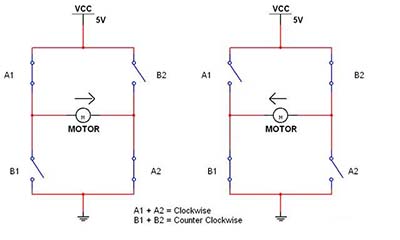
Figure 1: In the basic H-bridge, a quartet of switches controls current flow and thus motor direction as cross-pairs of switches on or off. Note that the upper switches are floating and not connected to ground.
schematic representations of the MOSFET
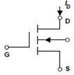
Figure 2: One of the common schematic representations of the MOSFET, with drain (D), gate (G), and source (S) terminals.
The IGBT is a bipolar transistor, also a three terminal device, but with an emitter and collector as connections for the current path being controlled. Like the MOSFET, it has a gate to control that path, Figure 3. As a bipolar device, it's very difficult to build an IGBT on a standard MOS IC process; thus, IGBTs are discrete devices. The IGBT combines the simple gate drive of a FET with the high-current/high-voltage handling capability of the bipolar transistor.
One of the common schematic representations of the IGBT, with collector (C), gate (G), and emitter (E) terminals.

Figure 3: One of the common schematic representations of the IGBT, with collector (C), gate (G), and emitter (E) terminals.
Note that many IGBT circuits also need a reverse-blocking (anti-parallel) diode which cannot be fabricated with the IGBT, so the IGBT+diode combination is often co-packaged and offered as a single module. Single-ended topologies such as boost-PFC power supplies do not need this diode, and use an IGBT alone.
The drive current needed at the gate to turn on either device varies, but is typically about 10% of the rated current of the device. Driving this current (sourcing) into the gate's capacitance fast enough for required turn-on speed, and pulling it out (sinking) for the turn-off cycle are two of the largest challenges in developing a complete motor-drive circuit, Figure 4 . In addition, for safety, electrical compatibility with low-voltage digital signals, or to “float” the upper device's driver, the path must often include galvanic isolation between the digital output of the controller's processor and the driver circuit.
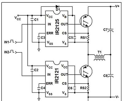
Figure 4: This gate-drive circuit controls a pair of IGBTs in a bipolar H-bridge from a low-level digital signal, for driving a motor in either direction (from International Rectifier AN-990).
Key parameters
As with most electronic components, there are a few primary parameters and performance specifications that determine the initial match between the device and the application. These are followed by a large number of secondary parameters and then by tertiary ones that, when taken as a group, point to a suitable choice. Of course, there is no single “best” choice, as any selection forces decisions with respect to the weighting of the many unavoidable tradeoffs of component selection (including cost, of course). For both devices, the top-level parameters are the current-handling and peak-voltage ratings, as these determine if a specific part can support the motor's load requirements.
For MOSFETs, the next critical parameters are on-resistance (RDS(on)) and gate capacitance. Lower on-resistance means reduced resistive loss and voltage drop when conducting, and thus reduced dissipation load and increased efficiency. Advances in MOSFET design have reduced on-resistance to tens of miiliohms—small, for sure, but still a potential problem when handling tens or hundreds of amps.
Gate capacitance determines the current and slew rate needed turn the gate fully on and off with the desired transition time (which relates to switching speed). The amount of current to be injected or pulled out is based on the basic equation I = C dV/dt; there's no way around that.
For IGBTs, the next critical specification is the on-state voltage drop Vdrop of about 2 V, which is the sum of the diode drop across the internal PN junction and its internal driving MOSFET; it never goes below a single-diode threshold value.
If these parameters were static, selection would be easier. But the reality is that both MOSFET RDS(on) and IGBT Vdrop are affected by temperature and current level, and power devices such as these do have significant self-heating. For MOSFETs, the voltage drop is resistive and proportional to current, and RDS(on) increases with temperature. For IGBTs, the drop is diode-like, increasing with the log of the current, and is relatively constant with temperature (Figure 5 ).
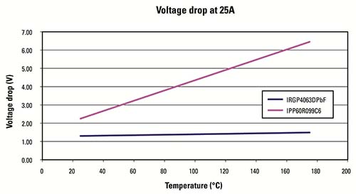
Figure 5: On-state voltage drop vs. temperature of two devices operated at the same current density. The IPP60R099C6 is a superjunction power MOSFET while the IRGP4063D is a trench IGBT (from International Rectifier AN-983).
In general, when comparing MOSFETs and IGBTs, the former offers higher switching speeds (MHz); higher peak current; and a wider SOA (safe operating area). But their conduction is strongly dependent on temperature and voltage rating; as the voltage rating goes up, the reverse recovery performance of their integral diode deteriorates, increasing switching losses. IGBTs are available with higher current ratings, and are rugged, but have slower switching speed; their lack of an internal reverse-recovery diode means you must find an IGBT co-packaged with a diode matched to your application.
For motor-drive applications, starting guidelines are that MOSFETs are a better choice at lower voltages and currents, and at higher switching frequencies; IGBTs are a better choice at higher voltage/current and lower frequencies. Caution: All guidelines have many exceptions, depending on the application's specifics. Since most motors need only lower-frequency operation (a function of the number of poles and the maximum rpm), IGBTs are a viable option for this application.
Thermal and packaging considerations
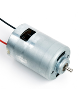
No discussion of MOSFETs and IGBTs for motor drive is complete without discussion of dissipation and packaging. Since motors involve power control, the switching component must be able to dissipate the inevitable heat that results from internal losses. The industry has standardized on a relatively few package sizes and types for these devices (D2PAK, D-Pak, TO-220, TO-227, and TO-262 for small/moderate power levels), which simplifies heat-sink and cooling options.
Thermal modeling of the package and its dissipation performance at the power levels is critical. Vendors provide detailed thermal models, and the basic modeling is fairly straightforward. Vendors also provide application notes that walk designers through the basics with examples. The initial modeling usually only requires a spreadsheet, but a more advanced thermal-analysis applications program may be needed to investigate heat-sinking and related options. Both MOSFETs and IGBTs can be paralleled to carry higher current or physically spread the thermal sources—often a need in motor drive—but each needs a different configuration of additional passive components to balance and equalize current flow.
There's more to modeling than the component's thermal situation. Even if you can get rid of enough of the heat from the MOSFET or IGBT to keep it below its SOA rating, that heat has to go somewhere. In some cases, there is an easy dissipation path to “outside,” but in many cases, the heat the device gives off becomes a problem for the rest of the PC board or box. Therefore, the thermal analysis must look at system-wide impact of dissipation, especially as many motor applications are in enclosed or challenging environments where ambient temperatures are high and cooling airflow is low.
Making the choice
There is no single “best” choice of individual model or even between a MOSFET or IGBT in most cases. The reality is that the decision is made on many performance parameters and their relative priority, as well as availability and cost.
Fortunately, there are many vendors of MOSFETs and IGBTs, although it can be overwhelming. If in doubt, start with a vendor that offers solid application notes on general design issue, supplemented with detailed designs (and their analysis) for specific applications that you can use as a starting point. Some vendors offer both MOSFETs and IGBTs, so they can provide a balanced assessment of the decision of which type of switch to use. Of course, a library of proven reference designs (layout, BOM) is also critical.
If the options seem confusing or overwhelming, a good strategy is to work closely with a distributor such as Mouser Electronics, who stocks a large selection of both types of devices from many major manufacturers such as Vishay, Fairchild, ON Semiconductor, ST Microelectronics, Infineon and more. From a single website, engineers can download datasheets, application notes, proven reference designs and even compare individual products to obtain a balanced assessment of the relevant attributes for their specific application.
Advertisement
Learn more about Mouser Electronics


