Battery fundamentals Part 3: The critical charging functions and parameters
Many primary protection features are integrated into a battery pack but there are many more system safety concerns that need to be addressed with a battery charging IC
BY GEORGE PAPARRIZOS
Summit Microelectronics
www.summitmicro.com
Part 1 can be found at: www2.electronicproducts.com/Fundamentals_of_battery_charging_Part_1-article-fapo_Summit_may2011-html.aspx Part 2 can be found at: www2.electronicproducts.com/Battery_charging_architectures_Part_2-article-fapo_Summit_jul2011-html.aspx
In Part 1 of this series we introduced the definition of the charging currents during the various Li+ battery charging phases. The maximum charging current capability and current range of a typical battery-charging IC will determine what battery capacities it can fully support. It is recommended that power dissipation under worst-case system conditions be analyzed to ensure that “advertised” charge current for a specific charger IC is feasible, since excessive temperature rise may lead to reduced current levels. Charge current accuracy is also very critical, since the more precise the current setting the less design headroom is required for the system. For example, in charging applications that utilize a USB (Universal Serial Bus) port as the power source, the host device needs to draw less than 100 mA or 500 mA to meet the USB2.0 specification, but at the same time the system would prefer to draw a current level that is as close to 100 or 500 mA as possible to accelerate the charging process.
The float (or battery regulation) voltage is the maximum voltage that the charge controller allows the battery to reach, limiting the overcharge of the battery. While the majority of Li+ battery packs are specified to use 4.2 V ±50 mV, there are new battery technologies that require as low as 3.6 V and as high as 4.4 V. Hence, a battery-charging solution with an adjustable battery regulation voltage can be useful for addressing many different battery packs (See Fig. 7 ). Another benefit of float voltage “programmability” is the increased system safety: a design may choose to use a lower default float voltage (such as 3.7 V) when the system is off, and many critical safety functions may not be active, and then adjust it to the final regulation level (such as 4.2 V) when the system is up and running. Float voltage accuracy also needs to be taken into account; a higher than expected float voltage level degrades the life of the battery and could allow the battery pack to enter an overvoltage condition, resulting in charge suspension. On the other hand, a lower than expected float voltage leaves the battery cell undercharged, thereby reducing the battery’s usable operating life.
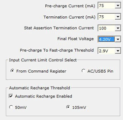
Fig. 7: Example of a programmable charging solution.
While many of the primary protection features (overvoltage, undervoltage, overcurrent, etc.) are integrated into the battery pack, there are many more system safety concerns that need to be addressed with a battery charging IC or other components, especially given the “sensitivity” of Li-ion battery chemistry and consumer perception (as a result of the few but significant accident reports). Taking steps to proactively address corner safety cases becomes especially important when certain safety standards need to be met, like the IEEE 1725 from the IEEE Power Engineering Society or safety standards set by the Japan Electronics and Information Technology Industries Association.
Critical safety features
One of the most critical safety features in handheld system designs is the monitoring of the battery cell temperature. High temperature levels are the main source of Li-ion instability, therefore battery packs incorporate a thermistor element that can monitor temperature levels and provide this information to the “outside” world. In response to this, many of the charging ICs have the ability to “read” this thermistor output and suspend charging when the cell temperature is outside a battery manufacturer’s specified range (usually 0 to 45C). Optimizing battery temperature monitoring for each battery pack is also possible with many of the new charging solutions, since they allow the independent adjustment of these temperature thresholds based on battery pack and thermistor specifications. Furthermore, system designs can now implement adaptive charging based on battery pack temperature, thereby allowing maximum safety and extended charging range at the same time. Such implementations allow the adjustment (reduction) of float voltage and/or charge currents during certain temperature ranges, as demonstrated in Fig. 8 .
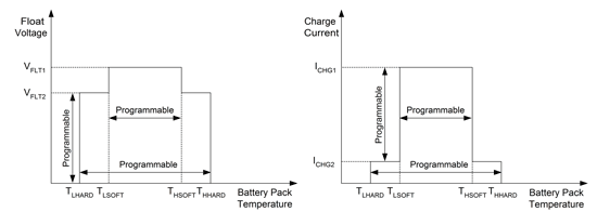
Fig. 8: Adaptive charging based on battery pack temperature.
Real-time monitoring
Another very important protection feature is the real-time monitoring of the input voltage level. The high adoption rate of the micro-USB connector and the popularity of USB charging have resulted in a flood of USB wall adapters which vary in quality and power ratings. With the convenience of universal (USB) charging comes the risk of consumers plugging a standard USB cable to a wall adapter that may be: a) poorly regulated, b) defective or c) under-rated in terms of power. A poorly regulated or defective power source may provide higher than allowable voltage levels to the portable device. The charging IC needs to be able to withstand such high-voltage dc levels, to suspend the charging process and most importantly to isolate the system so that it does not get exposed to over-voltage or over-current conditions (most systems cannot survive higher than 5-V conditions). In the case of an under-rated wall adapter, the system may try to draw more current than is available from the power source, resulting in a noncharging situation, consumer frustration and eventual service calls. Automatic input current limit (patent granted) can address this design challenge by detecting the maximum current capability of the ac/dc adapter and automatically programming the devices’ input current limit accordingly.
Charge safety timers are also required in portable system designs to prevent charging a dead battery for an excessive period of time. These timers provide protection against defective battery cells by suspending charging when the duration of the charging process exceeds the time expected under normal charging (and operating) conditions. The timer duration is adjustable in most charging ICs, since it needs to allow some design flexibility given that different systems will have different load profiles, and therefore different current levels going into the battery for charging. It is also common for the timers to independently monitor charge duration for both the pre-charge and the complete-charge phase to ensure faster detection of abnormal charging conditions.
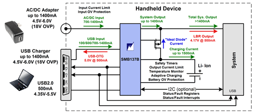
Fig. 9: Charging solution with comprehensive safety features.
Last but not least, protecting the battery from an over-voltage condition is one of the main functions of the protection IC located inside the battery pack. However, having secondary protection (see Fig. 9 ) on the battery charger IC allows for higher system reliability and meets the most stringent safety requirements in the industry. ■
Advertisement
Learn more about Summit Microelectronics


