BY MARTIN ROWE, Senior Technical Editor, Test & Measurement
EDN and EE Times
www.edn.com , www.eetimes.com
5G New Radio (5GNR) will rely heavily on beam steering to maximize data throughput, especially when used to send and receive millimeter-wave (mmWave) frequencies. Starting at about 24 GHz, mmWave signals offer tremendous bandwidth as compared with microwave signals. But that comes at a price: signal losses. Beam steering, also called beamforming, minimizes losses by concentrating signals at their targets rather than transmitting signals in all directions. The technique uses multiple antennas that can be simulated through software.
The array antenna shown in Fig. 1 consists of 256 antennas arranged in a 16 × 16 grid transmitting 64-QAM data signal at 28 GHz. Keysight Technologies joined with Anokiwave and Ball Aerospace to demonstrate beam steering at the 2018 International Microwave Symposium.
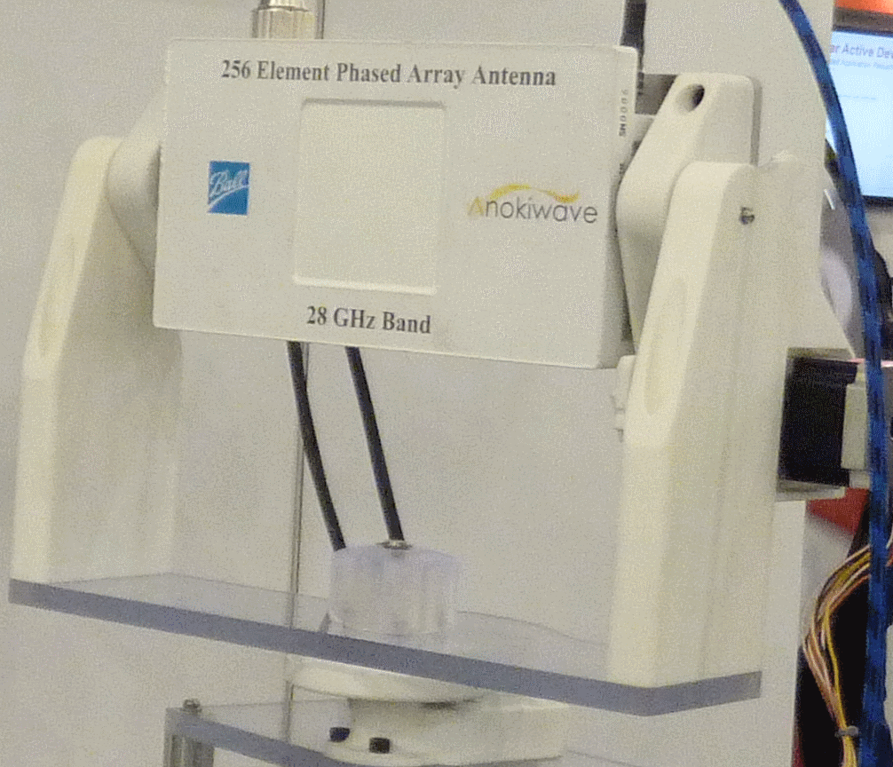
Fig. 1: An array of 256 antennas uses a 16 × 16 grid to steer the beam toward a target. Image: Martin Rowe.
The array is driven by 64 Anokiwave quad-core ICs, wherein each IC drives four antenna elements. The antenna can form a single steerable beam using all 256 elements or four independently steerable beams using 64 elements each.
Beam steering can use analog (RF), digital, or hybrid approaches. In analog beam steering (Fig. 2 ), a single analog-to-digital converter (ADC) provides the signal for eight antennas.
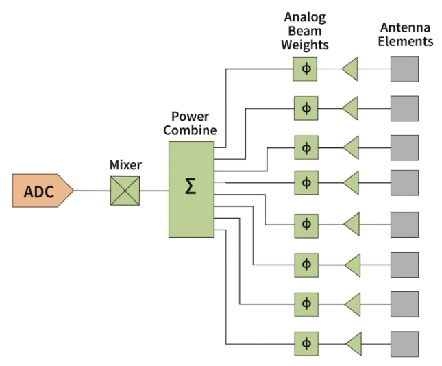
Fig. 2: Analog antenna systems use a single ADC for all antennas. Image: Anokiwave.
While analog beam steering minimizes the number of ADCs, it has problems such as phase shift, RMS phase error, and RMS amplitude error as a function of frequency. Plus, all signal processing — phase shifting and signal attenuation/amplification — must take place at the antenna. Thus, it’s practical only with highly integrated ICs. You also lose flexibility in the number of beams that can be formed.
A full digital signal chain uses a dedicated ADC/DAC pair per antenna for transmit/receive. Such an architecture provides the most beamforming flexibility, but it’s impractical. The high cost of the ADCs and excessive heat that they generate make digital beam steering unattractive. Thus, a hybrid approach is taking hold. Fig. 3 shows the same eight antennas from Fig. 2 driven by two ADCs handling four antennas each. This approach provides good beamforming flexibility while eliminating the challenges of digital beam steering.
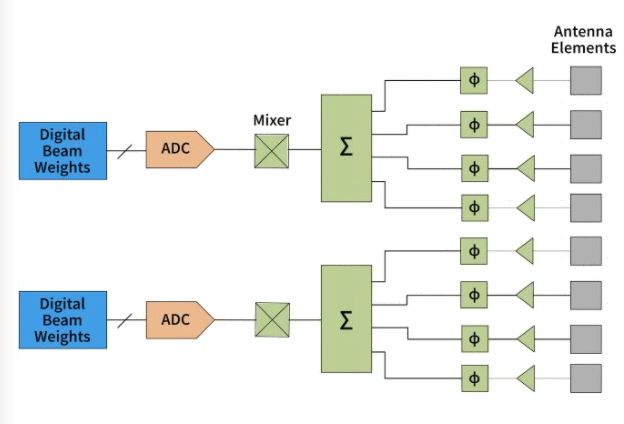
Fig. 3: In a hybrid system, each ADC generates signals for multiple antennas. Image: Anokiwave.
Logan Minard, customer engineer at Anokiwave, explained the signal chains used in the company’s ICs (Fig. 4 ): “Common” refers not to a common signal return but to the ADC and DAC circuits included in the transmit and receive signal chains, respectively. Analog signals from the ADCs go to Wilkinson power dividers, followed by amplitude and phase control and a power amplifier (PA). Another switch connects the signal to the antenna.
On the receive side, the received signal first comes through a low-noise amplifier (LNA), then through a Wilkinson combiner and temperature compensator, which adjusts signal gain based on temperature, he continued.
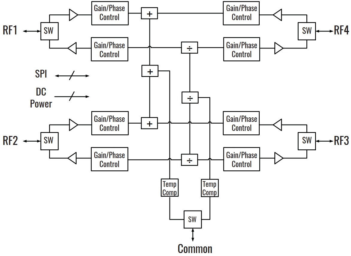
Fig. 4: A block diagram of the Anokiwave AWMF-0108 shows the transmit and receive signal chains. Image: Anokiwave.
In the Microwave Symposium demonstration, the beam steers ±30° from boresight, though the array is capable of steering up to ±60° from boresight. “Once you get beyond 60° from boresight, excessive scan loss occurs, making the antenna gain drop below acceptable levels,” said Minard.
Designing a beam-steering system requires simulating the antenna array, the radio components (amplifiers, filters, mixers, phase shifters, etc.), and the transmission channel. How do you get started?
Modeling phased-array antennas and other 5GNR components doesn’t mean that you have to develop your own models. Modeling and simulation software from several companies can crunch the numbers for you. Just feed them your design parameters, including:
- Frequency
- Antenna gain
- Sidelobe level
- Material property such as permittivity
- Array geometry
- Weighting of each antenna in an array
- Phase-shift equalization levels
To design an array, start by modeling a single antenna element, then scale those characteristics up to form an array. Fig. 5 shows models of elements, an 8 × 8 array, and the sidelobe levels from the array.
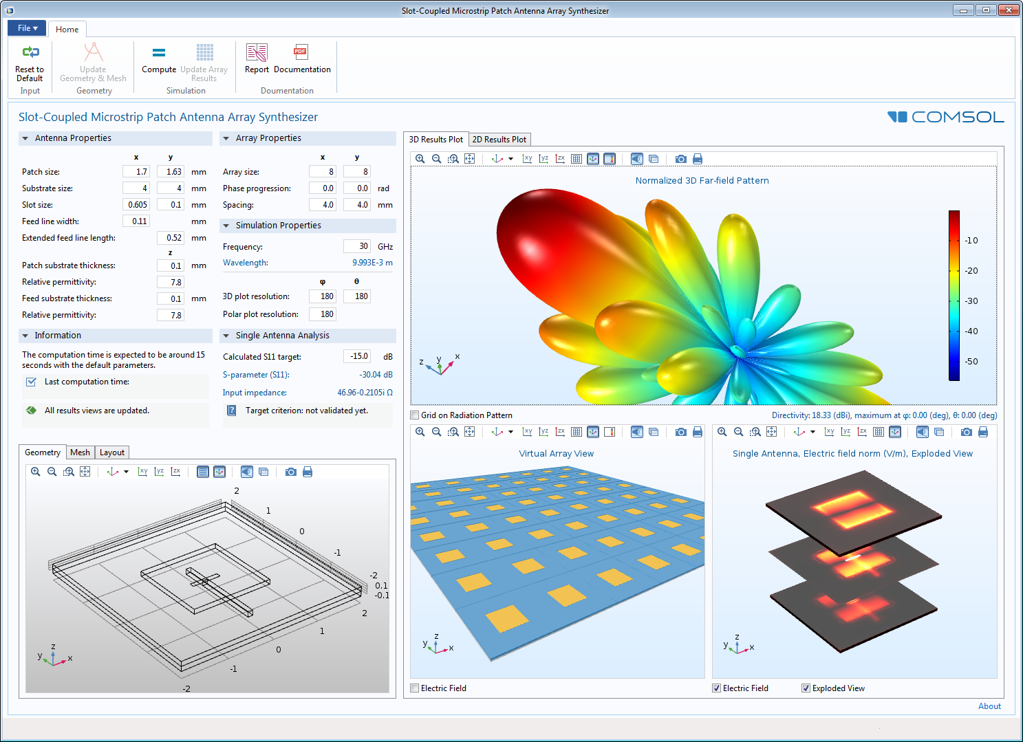
Fig. 5: Using COMSOL Multiphysics software, you can model a slot-coupled microstrip patch antenna array. Image: COMSOL Multiphysics.
Simulation software lets you enter a range of parameters and step through them while viewing the signal pattern. In MATLAB’s Antenna Toolbox, you can enter a range of values in a simulation app or you can write scripts to automate the process and see the results as parameters change.
Software represents the simulated antenna patterns using colors and distances from the antenna. The colors in Fig. 6 highlight the directivity from a single element in units of decibels relative to an isotropic antenna (dBi).
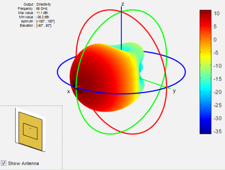
Fig. 6: Software such as MATLAB simulates the radiated pattern from a single antenna in units of dBi. Red indicates the strongest difference of signal relative to the isotropic antenna. Image: MathWorks.
While it’s important to know the expected response of a phased-array antenna, what happens if a cell should fail? “Simulation software can produce volumetric and surface plots of each dimensional component of an electric field, which can help to diagnose the abnormal behavior of networks and individual array elements,” said Jiyoun Munn, technical product manager of the RF Module at COMSOL.
Phased arrays may consist of sub-arrays, as in the case of hybrid systems. “Failed subarrays can also be simulated,” added Rick Gentile, product manager for Phased Array System Toolbox and Signal Processing Toolbox at MathWorks. “With a failed subarray, many elements may be missing because a transmit/receive module is shared.”
Phased arrays will likely become commonplace as 5G rollouts begin. Larger arrays, such as 64 × 64 and larger, will be used in base stations and for mmWave frequencies in small cells. Smaller arrays such as 2 × 2 or 4 × 4 will likely be incorporated into handsets.
Advertisement
Learn more about Electronic Products Magazine


