Design Considerations
Plug-in Hybrid Electric Vehicles (PHEV) and Battery Electric Vehicles (BEV) are two quickly emerging technologies which use powerful electric motors and high voltage battery packs as the propulsion and energy sources. Since batteries have a finite energy capacity, PHEV and BEV must be recharged on a periodic basis, typically by connecting to the power grid in some form. For most users, Level 1 charging (120 VAC at 15A-20A) will be the most available power supply that all on-board chargers should be capable of handing as it will be easily accessible to all users. In its current state, most users would prefer to take advantage of the faster charging Level 2 (240 VAC at 40A) that will allow for faster charging times compared to the Level 1, but will require a larger power source to supply the appropriate current and voltage. By having the capacity to utilize both types of charging, you provide the user with more flexibility in their charging options and a larger number of locations where a charge can be delivered.
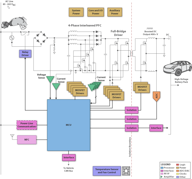
The Level 1&2 charging system for these vehicles consist of an AC/DC converter to generate a DC voltage from the AC line. This incoming power needs to undergo power factor correction (PFC) to boost the power factor to meet regional regulatory standards. At the heart of the inverter is a real-time C2000 microcontroller. This controller is programmed to perform the control loops for all necessary power management functions, including AC/DC with PFC and DC/DC to create the necessary charge profile for the battery. The C2000 controller contains advanced peripherals such as high precision PWM outputs and ADCs, and is designed to read the ADC and adjust the PWM within a single clock cycle making real time control possible.
For safety reasons, isolation between the processor and the current and voltage is also required, as well as on the communications bus to the outside world. TI digital isolators have logic input and output buffers separated by TI’s silicon dioxide (SiO2) isolation barrier, providing 4kV of isolation. Used in conjunction with isolated power supplies, these devices block high voltage, isolate grounds, and prevent noise currents from entering the local ground and interfering with or damaging sensitive circuitry. High-performance analog parts are also available to provide critical system functions such as MOSFET drivers, sensor feedback, chip power supplies, and communication transceivers.
Communications for a Level 1&2 on-board charging system would be application specific. It would be at the desire of the consumer as to whether or not they wanted such a system to connect to the power grid. Level 1 charging will not likely be common in the public domain as it will be most prominent in the home charging area. Level 2, on the other hand, would benefit from the integration of Power Line Communication (PLC) or a wireless protocol to enable direct communication between the charging station and the utility companies. Both charging levels have the option for the user to connect to a smart meter type application or log data onto their Home Area Network (HAN) for personal uses via either the PLC or wireless protocols.
Additional communication options provide the user with more flexibility in order to fully benefit from all the advantages of having a plug-in vehicle.
Click here for additional information
Download Full Block Diagram Below
Advertisement

Learn more about Texas Instruments


