Breaking ground loops to reduce transmission errors
A single-chip USB isolator can stop transformer-coupled current from flowing and prevents ground loops through interfaces
BY NIKOLAS LEDOUX
Applications Engineer, Analog Devices
www.analog.com
Transmitting data over long distances is fraught with potential problems. A ground loop can be a source of interference that can induce a noise voltage between the grounds on either end of the transmission. If this voltage is large enough, it can cause data errors at the receiver. This article will explain how ground loops occur and discuss how galvanic isolation has been used to eliminate them.
Ground loops are discussed in the context of USB throughout this article, but other interfaces, such as RS-232, RS-485, CAN, etc., are also susceptible to ground loops. Though this discussion focuses on breaking ground loops as a motivation for isolating these interfaces, there are other important considerations, such as operator safety and the protection of electronics, that necessitate isolation.
Ground loops are, as their name suggests, a physical loop in a system’s grounding scheme resulting from multiple ground paths between circuits. These ground paths can act as a large loop antenna that causes noise to be picked up from the environment, inducing currents in the grounding system. The 50/60-Hz magnetic field from ac-power is a common source of the noise that ground loops pick up.
A distributed grounding system can also allow ground voltage noise from sources at one location to cause ground currents to flow in the ground loop. Since grounds are low impedance, the noise currents are often large. Hundreds of millivolts of noise can cause amps of current to flow through the ground loop.
Figure 1 shows an example of how ground loop interference can occur in a generic data transmission path. Device 1 drives a single-ended signal that Device 2 receives. The signal line is grounded at either device. For example, the ground connection could be the shield of a coaxial cable. There is a second low-impedance connection between the devices’ grounds through the safety grounds of their power supplies. These two ground connections create a large loop, which picks up a noise voltage from the magnetic field of a nearby interferer. This interference degrades the signal that is seen by Device 2 and hinders the transmission.
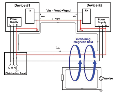
Fig. 1: An example of how ground loop interference can occur in a generic data transmission path.
While designers should be careful to avoid loops by using a single grounding location, some interfaces require ground connections at each transceivers. This ground connection needs to be broken while maintaining the flow of information from the transmitter to the receiver. In other words, the two devices need to be galvanically isolated.
One possible method of breaking the ground loop is using an optocoupler, as illustrated in Fig. 2 . Device 1 drives the optocoupler’s LED, which excites a current in a phototransistor. The ground connection through the cable is removed, which prevents noise currents from flowing between Device 1 and Device 2 and information is transferred in the form of light.
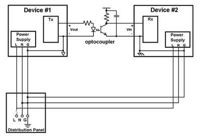
Fig. 2: A possible method of breaking the ground loop is using an optocoupler.
This approach has limitations as the performance and complexity of the interface increase. Optically isolating interfaces can become complex, expensive and require a significant amount of board space.
Optocouplers have significant propagation delays, making them only useful for low-speed signals. Power dissipation in the LED and pull-up resistor can become significant as multiple optocouplers are used. Digital isolation technology can be used to break ground loops without compromising the interface’s performance, and with relatively few components in simple application circuits. Digital isolators are non-optical isolators, which use CMOS interface ICs to transfer information through capacitive or magnetic coupling.
Connecting two ac-powered devices with a USB cable can cause a ground loop that disrupts communications through the bus. USB communication occurs over a single bidirectional differential pair (the D+ and D signals in Fig. 3 ). A host device controls the bus and communicates with a peripheral. The directionality of data packets is established through the USB protocol, not by control signals.
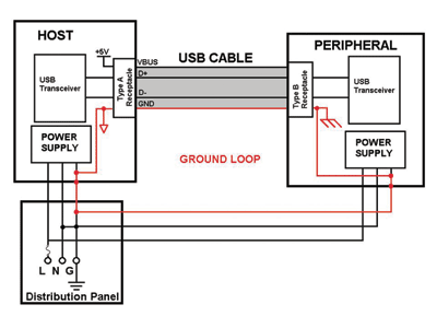
Fig. 3: USB communication occurs over a single bidirectional differential pair (the D+ and D–D- signals).
The host device provides power and ground to the peripheral device. This ground connection in a USB cable and the safety grounds of the host and peripheral forms a ground loop which can cause the peripheral’s ground potential to move relative to the host’s and result in unreliable communication.
Isolating a USB port to eliminate the cable ground connection is inherently difficult because there are no control signals to indicate whether data is being transmitted downstream (to the peripheral) or upstream (to the host). Without access to the internal signals of the serial interface engine (SIE) controlling the bus, the only way to determine the data’s directionality is through the bus transactions. The SIE’s signals may not be available because the SIE is often integrated into processors.
There are several possible approaches to isolating USB. For example, the challenges of isolating D+ and D can be avoided by using an external SIE that is controlled by a serial interface with unidirectional signals, such as SPI. Unidirectional signals are easier to isolate.
Figure 4 illustrates this approach. The propagation delay of optocouplers would severely limit the speed of the isolated SPI, so a quad channel digital isolator is used. The external USB controller transmits data from its buffers, which are filled through the SPI interface. Although the external SIE will transmit data at the fastest peripheral’s fastest possible data rate, the effective data rate of the bus is limited by the controller’s ability to keep the SIE’s buffers full. The propagation delay of the digital isolator may be a bottleneck in this case. This approach is costly in terms of board space, because of the external SIE and can require modifications to the peripheral’s drivers.
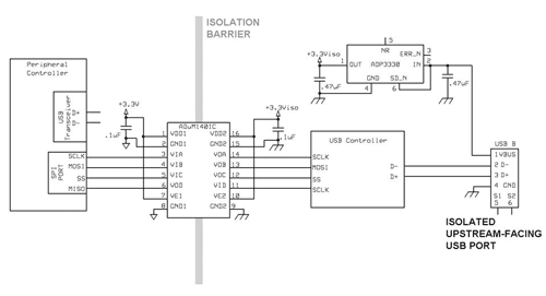
Fig. 4: External SIE that is controlled by a serial interface with unidirectional signals
A simpler approach is to directly isolate the D+ and D lines with an ADuM3160 single-chip USB isolator, as shown in Fig. 5 . This digital isolator requires no modifications of either the host or peripheral’s drivers. Its internal logic determines the directionality of D+ and D by the USB protocol and activates and deactivates drivers accordingly. A 2.5-kV isolation barrier splits the ground connection through the USB cable that would cause a ground loop otherwise.
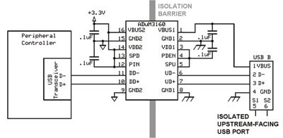
Fig. 5: Simple approach for isolating the D+ and D–D- lines.
A simple hardware simulation of a ground loop was designed to illustrate the risks of ground loops in wired communication and the effectiveness of galvanic isolation at breaking ground loops. The test setup created a ground loop with connections through the USB cable and power supplies of a USB hub and a peripheral, which were controlled by a laptop.
This setup coupled a 60-Hz signal derived from the ac-power line to the ground line with a transformer. This was analogous to the magnetic field from power lines inducing noise in a ground loop, since it relied on the same noise source. A variable series resistance made the current through the ground loop adjustable. The voltage from the hub’s ground to the peripheral’s ground was observed and the current through the ground loop was increased until it disrupted communications to the hub.
Two different peripheral devices consistently lost communication with the hub and laptop when their ground rose to over 1 Vrms above the hub’s ground due to the simulated ground loop current. Isolating the hub’s port with an ADuM3160 USB isolator broke the ground connection through the USB cable and prevented the transformer-coupled current from flowing. This effectively restored communication between the PC and either peripheral and illustrates how digital isolation can be employed to prevent ground loops. ■
References
Noise Reduction Techniques in Electronic Systems, Wiley-Interscience; 2nd edition (March 9, 1988)
AN-375 application note, “ADM2xxL Family for RS-232 Communications,” by Matt Smith, PDF link: http://www.analog.com/static/imported-files/application_notes/527881158649405705232480454AN375.pdf
AN-740 application note, “iCoupler® Isolation in RS-232 Applications,” by Sean Clark and Ronn Kliger
AN-770 application note, “iCoupler® Isolation in CAN Bus Applications,” by Ronn Kliger and Sean Clark, PDF link: http://www.analog.com/static/imported-files/application_notes/396914861238030599415561924AN770_0.pdf
“Digital Isolator Simplifies USB Isolation in Medical and Industrial Applications,” by Mark Cantrell of Analog Devices, (June 2009)
Advertisement
Learn more about Analog Devices


