Here are some solutions for IEEE802.3at-compliant PSE design
BY DANIEL FELDMAN
Microsemi, Irvine, CA
http://www.microsemi.com
A number of special requirements and challenges emerge when implementing the latest high-power IEEE 802.3at Power over Ethernet (PoE) technology in power-sourcing equipment (PSE) used to power a growing variety of portable platforms. The pending high-power PoEPlus standard is poised to actually eliminate the need for batteries in notebooks, thin clients, and other remote/mobile products. Achieving this, however, requires a more than doubling of the power-delivery capabilities of the earlier IEEE 802.3af standard, with important chip- and system-level implications.
Overall power consumption and power concentration are two key parameters that must be considered when designing PSE platforms for powering company-wide applications such as laptops. There have traditionally been two PSE supply options: integration of PoE into the Ethernet Switch (making it a PoE switch), or adding a PoE injector (also known as a midspan) between an existing non-PoE-capable Ethernet switch and a powered device (PD).
The midspan is connected in cascading fashion to an existing Ethernet switch or hub, enabling a network to be scaled to support PoE without requiring a switch upgrade. Midspans also diminish heat concentration and, by having only the necessary power available for the solution, are a green alternative to PoE switches.
In many cases, a smart combination of low- and high-power devices and the use of midspans in combination with PoE switches can achieve the right balance for cost-effectively servicing these new high-power applications. Given the amount of raw power needed by PoE, and especially PoEPlus, power dissipation and power management are crucial components of PoE systems. This can only be achieved effectively by an SoC approach, which does not necessarily mean complete integration. Achieving design objectives requires the use of ICs that are capable of minimizing power dissipation while delivering highly responsive and agile power management.
How much power is enough?
PoE allows the transmission of Ethernet data and smart dc power over the same cable. Created in 1999 by PowerDsine, PoE started as a proprietary mechanism, but since 2003 it is normally associated with IEEE802.3af-2003, an IEEE standard. While not a revolutionary idea (Bell had power and data in telephony systems in 1875), unlike its predecessors, PoE is a smart-power technology, in which the PSE applies power only to compliant PDs, monitors and limits the maximum power consumed by each PD, and electrically disables the PDs in case of a physical disconnection or a malfunction (short, overload, etc.).
Almost as soon as IEEE802.3af-2003 was ratified, it was clear that the 12.95 W it allowed PDs to consume was not enough, and that a new standard was necessary. In November 2004, the IEEE802.3 created the PoE Plus study group, which later became the IEEE802.3at Task Force, chartered with augmenting the amount of power available to PDs. The IEEE802.3at is expected to complete its work in the second half of 2009. IEEE802.3at-draft4.0 determines:
PSEs must output at least 30 W per port (up from 15.4 W).PDs may consume up to 25.5 W (up from 12.95 W).Cabling of CAT5e or better is required (versus CAT3).The PSE output voltage range is from 50 to 57 V (raising the minimum from 44 V).The maximum ongoing current is 600 mA (in contrast with 350 mA).Ac and dc disconnection methods are still allowed.

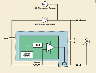
Fig. 1. PSE circuitry, ac disconnect.
New IC architectures support high-power PSEs
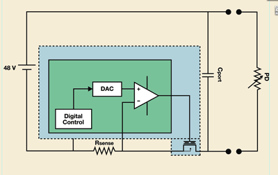
The typical circuitries in a PoE PSE are depicted in Figs. 1 and 2 . As can be seen, current that goes from the PSE power supply passes through:
An FET, used to control that maximum current running through the cable.A sense resistor, used to measure the current (in some implementations this is implemented via a FET).An ac disconnect diode, in systems using ac disconnect (dc disconnect systems do not require a diode).

Fig. 2. PSE circuitry, dc disconnect.
This means that the power dissipated per port will be I2 x (RSENSE + RDSon (FET)) + I x VFORWARD (ac disconnect diode) . The logic used to perform PoE functions may or may not be a major power consumption source, depending on the specific technology used and the number of ports served by the logic (4-port ICs, for example, use roughly three times more power than 12-port ICs for the logic section).
The simple increase in current from 350 to 600 mA could create serious issues for PoE switch makers. PoE PSE ICs built for IEEE802.3af had 2 Ω of RSENSE and 0.5 Ω of RDS(on) (FET), which means solutions dissipated 0.3-W/port in dc disconnect on the resistors and FETs.
Smart PoE PSE ICs built with IEEE802.3at in mind have much lower sense resistors (0.5 Ω) and have external (or very low resistance internal) FETs (0.1 Ω), which allow the power dissipated to be a lot lower: 0.07-W/port in IEEE802.3af or 0.22-W/port in IEEE802.3at, for dc disconnect.
It is important to note that not all manufacturers can support dc disconnect implementations.
Another consideration for high-power PoE system design is the ability of the PoE IC to deliver fast reaction times in managing multiple power supplies, and how accurately the IC can allocate power.
IEEE802.3af-compliant PSEs were typically built with full power per port in some cases (with or without redundancy) but with less than full power per port in most systems. For example, a 24-port PSE would require 400 W to support 15.4-W (plus losses) per port, but several suppliers offer PSEs with 200 W for 24 ports, or 7.5 W average. While enough for most applications including a mix of IP Phones and WLAN access points, applications deploying mainly network cameras or WLAN access points would require a full power PSE.
The same principle applies to IEEE802.3at-compliant PSEs, but with a big difference: while some IEEE802.3af applications could require full power/port, IEEE802.3at applications do not normally require full power on any single port, and definitely are less sparse then IEEE802.3af applications. In addition, IEEE802.3at PSE’s can also be used to power IEEE802.3af devices.
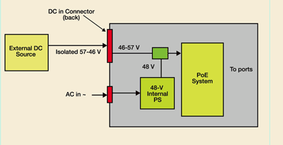
These factors, combined, bring about the need for a different power architecture in IEEE802.3at PSEs, one in which PSEs possess an internal or a default power supply, and additional power supplies can be added according to the actual customer needs. The additional power supply has an extra advantage: it can serve as a backup for the highest-priority ports in the system, and in the event of even a single power-supply failure, the system will continue working.
Managing several power supplies requires a very fast reaction by the PoE ICs managing the power budget. It also demands high accuracy in the allocation of power. The allocation of power can be done either in a dynamically (that is, according to the power consumed by the device), or in a statically or pseudostatically (in which the device communicates to the PSE via either hardware classification or the new layer 2 classification present in IEEE802.3at-draft 4.0. Figure 3 depicts a PSE with two power supplies.

Fig. 3. PSE with two power supplies.
IEEE802.3at PoEPlus brings numerous opportunities for engineers to create innovative PSEs and PDs. To support these efforts, PoE ICs have evolved to deliver lower power dissipation and significantly faster, more-agile, and more-accurate power management. The proper technological choices in these critical areas can make a huge impact on the cost to deploy and to run PoE systems, and should be carefully evaluated during the migration to IEEE802.3at ■
Advertisement
Learn more about Microsemi


